This sample demonstrates some HDR lighting effects using floating-point textures. Integer texture formats have a limited range of discrete values, which results in lost color information under dynamic lighting conditions; conversely, floating-point formats can store very small or very large color values, including values beyond the displayable 0.0 to 1.0 range. This flexibility allows for dynamic lighting effects, such as blue-shifting under low lighting and blooming under intense lighting. This sample also employs a simple light adaptation model, under which the camera is momentarily overexposed or underexposed to changing light conditions.

| Source: | (SDK root)\Samples\C++\Direct3D\HDRLighting |
| Executable: | (SDK root)\Samples\C++\Direct3D\Bin\x86 or x64\HDRLighting.exe |
Light in the real world has a very high ratio between highest and lowest luminances; this ratio is called dynamic range and is approximately 1012:1 for viewable light in everyday life, from sun to starlight; however, the human visual system is only capable of a dynamic range around 1000:1 at a particular exposure. In order to see light spread across a high dynamic range, the human visual system automatically adjusts its exposure to light, selecting a narrow range of luminances based on the intensity of incoming light. This process is not instantaneous, as you'll notice when entering a dark building on a sunny day, or vice versa. This delayed exposure adjustment is referred to as light adaptation, and can be simulated in a real-time application.
Computer displays and print media have a dynamic range around 100:1, so compromises will have to be made when trying to display a scene with a higher dynamic range; this sample borrows from a technique originally developed for use in photography called tone mapping, which describes the process of mapping an HDR image into a low dynamic range space. Tone mapping effectively produces the same effect as the automatic exposure control which happens in the human visual system.
Finally, when a bright light strikes a lens, certain aberrations naturally occur, including bloom and star effects shown in the following image. If high-intensity light values are not discarded during the render process, these effects can be produced after the scene has been rendered to add an additional level of realism to the image. Because these are post-process effects, the time required to produce them depends only on the screen resolution, regardless of scene or lighting complexity.

This sample uses Direct3D 9 floating-point textures to store HDR lighting information for the scene. Integer texture formats are clamped from 0.0f to 1.0f in the pixel shader, but floating-point textures are allowed to contain any value, bound only to the constraints of available bits for mantissa and exponent.
The algorithms described in this sample are based very closely on the lighting effects implemented in the following references.
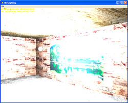
For this sample, scene objects are textured with normal integer format textures, but the sphere objects representing lights are shaded with a high range of values, effectively creating emissive lights. All objects in the scene are shaded using an illumination model that calculates ambient, diffuse, and specular lighting based on the position and intensity of the lights; because these lights be assigned high values, the resulting colors of illuminated objects can extend far beyond the 1.0f cutoff. If a floating-point texture is not used to capture these HDR values, this light data will be lost, and the scene will appear overexposed, as in the following figure.

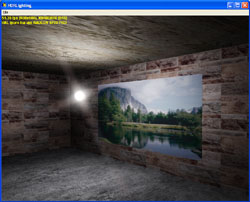
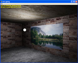
If, instead, the scene is rendered onto a floating-point surface, the HDR information will be stored and the scene can then be tone mapped to an appropriate low dynamic range for display, as shown in the following figure.

The following figure shows the top-level flow diagram for the sample. The scene is first rendered onto a floating-point texture, which has the same dimensions as the backbuffer. Because the scene will be sampled several times to create the post-processing effects, a good first step is to scale down the scene to minimize the number of pixels the shaders must sample. This has the added benefit of making post-process effects larger when their associated textures are scaled up to full size. The scaled scene texture is processed to measure the average luminance of the scene. Using this average luminance value, it is possible to determine which pixels in the scene will be bright after the scene has been tone mapped to a low dynamic range. By excluding all color data in the scene except brightly-lit areas, a bright-pass filtered copy of the scene is created that can be used as the source of post-process lighting effects.

The scene in this sample is rendered using a pixel shader to control the ambient, diffuse, and specular contribution of each light at every pixel. Because the lights for the featured scene are very bright, most of the pixels have per-channel color components above the 0.0 to 1.0 range displayable by the graphics card. Therefore, this texture appears mostly white when viewed directly. However, the color information above 1.0 is not lost, but simply needs to be tone-mapped into the 0.0 to 1.0 range. During a final pass, the scene is tone-mapped to the desired luminance range, and the post-process image effects are blended on top of the scene to create the final image.
Before your program can scale the intensity of your scene, it will need to determine how bright the scene is to begin with. The goal is to calculate a good estimate for the average scene luminance while minimizing the amount of time spent making the calculation. The calculation can be sped up by reducing the number of sampled texels, but you risk missing bright areas with a sparse test pattern. The approach used in this sample is to first scale the scene by 1/4 x 1/4, using the average of each 4 x 4 block of texels to down-sample. This scaled texture is also used to create the source textures for the lighting effects, so it is important that the scale operation is precise, to avoid flickering artifacts as the camera moves around the scene.
The process used to measure the average scene luminance and perform tone mapping is featured in the whitepaper Photographic Tone Reproduction for Digital Images, from which the following luminance equation is taken.

The average scene luminance used for later calculations is the antilogarithm of the average log values for all sampled pixels. Delta contains a small value to handle the case of pure black texels. This equation is implemented using four pixel shader passes called from the MeasureLuminance method, as follows:
By keeping the calculation result inside a 1 x 1 texture, the calculations which require the average luminance value can be done completely on the video card without requiring any AGP transfers.
Exposure control is the process of finding an appropriate low dynamic range view of the HDR scene. In a physical lens system, the aperture is adjusted to limit the amount of light entering the system. The process used in computer graphics to emulate exposure control is commonly called tone mapping, which refers to the process of mapping an HDR image space onto a low dynamic range space suitable for video display. Unlike exposure control, all the high range data is available for use when tone mapping; so, depending on the operator used, the image may contain more detail from bright and dark areas simultaneously than would be possible using a traditional camera.
After the average scene luminance has been calculated, the HDR scene texture can be scaled according to a target average luminance, represented by alpha in the following equation:

This equation simply produces a linear scaling of the scene luminance centered around the target average luminance for the final scene; however, the resulting values have not yet been compressed to fit within the low dynamic range of 0.0 to 1.0 viewable on the monitor. The following tone mapping operator performs the desired compression.

The human visual system does not adjust instantly for changing light conditions, and this behavior can be easily simulated by slightly extending the tone-mapping calculations. The luminance value to which the user is currently adapted is used instead of the average scene luminance within the tone-mapping equations. This adapted luminance value is stored in a 1 x 1 texture and is adjusted each frame to slowly track the measured scene luminance, as shown in the following code snippet:
float fNewAdaptation = fAdaptedLum + (fCurrentLum - fAdaptedLum) * ( 1 - pow( 0.98f, 30 * g_fElapsedTime ) );
For example, if the camera is stationary, the adapted luminance will eventually match the measured luminance, resulting in tone-mapped output identical to the output when adaptation is disabled. However, if the camera is moved to focus on an area of different lighting magnitude, the image will appear over- or underexposed while the viewer adjusts to the new lighting conditions. The adaptation model used in this sample is not intended to be a realistic model of human adaptation, which can take longer than a half hour for full dark adaptation.
Tone mapping is performed in two places within the code: once in Render as part of the final shader pass to compose the glare textures onto the scene, and once as part of the bright-pass filter. The bright-pass filter uses tone mapping to first determine what areas of the final scene image will be bright, and then it excludes the remaining data. Because HDR lighting effects are relative to the current exposure, these effects can be performed on a tone-mapped image and added directly to the scene output. This procedure offers the advantage of being able to use integer textures for glare generation.
As shown in the following code snippet, the bright-pass filter first maps the scene to a desired middle gray target luminance before subtracting out the dark areas. The tone mapping operator which transforms the scene luminance to the 0.0 to 1.0 range is modified slightly from the last equation. Instead of dividing the luminance by one plus the luminance, an offset value replaces one in the equation. As this offset value increases, the relative separation between bright and dark regions of the scene also increases.
// Determine what the pixel's value will be after tone mapping occurs
vSample.rgb *= g_fMiddleGray/(fAdaptedLum + 0.001f);

// Subtract out dark pixels
vSample.rgb -= BRIGHT_PASS_THRESHOLD;

// Clamp to 0
vSample = max(vSample, 0.0f);

// Map the resulting value into the 0 to 1 range. Higher values for
// BRIGHT_PASS_OFFSET will isolate lights from illuminated scene
// objects.
vSample.rgb /= (BRIGHT_PASS_OFFSET+vSample);
Before the bloom is performed, the bright-pass filtered image is scaled and blurred down to 1/8 x 1/8 scale of the original scene texture. The bloom pass is simply a two-pass separable horizontal and vertical Gaussian blur of the scaled bright-pass filtered scene. As shown in the following figure, the texture is first blurred along the horizontal, then the horizontally-blurred texture is blurred along the vertical to complete the process. As part of the final scene pass, the bloom texture is scaled to the size of the back buffer using bilinear filtering and added directly to the output of the scene.

The star effect may require as many as three passes to render each of the star lines. The star patterns used in this sample require as many as eight lines, resulting in a potential cost of 24 passes to render fully. The GlareDef.h file defines characteristics for the various star types, including the number of lines, line directions, and chromatic offsets. As shown in the following figure, once all the individual directional lines have been rendered, the average texel value across the individual line textures is used to create the final composite star texture. This composite texture is scaled and added directly to the final scene image.
