| Source: | (SDK root)\Samples\C++\Direct3D\HDRDemo |
| Executable: | (SDK root)\Samples\C++\Direct3D\Bin\x86 or x64\HDRDemo.exe |
This sample application is intended to complement existing HDR (High Dynamic Range) samples by showing the many intermediary processing steps that make up a typical HDR rendering path in a Direct3D application. Whilst implementing HDR rendering is not the most complex of algorithms, it does have a large number of steps involved in the composition of the final image displayed to the user.
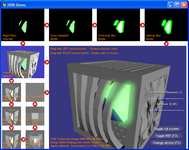
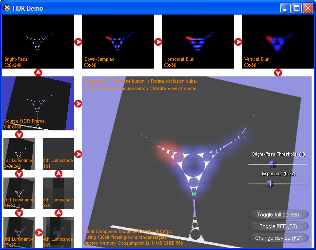
The above screenshot shows a typical view of the application. To correctly interpret the display, follow the white-on-red arrows linking each of the cells together - they indicate the order in which the steps are completed. The image that would normally be shown to the end-user is the largest cell in the bottom-right of the window.
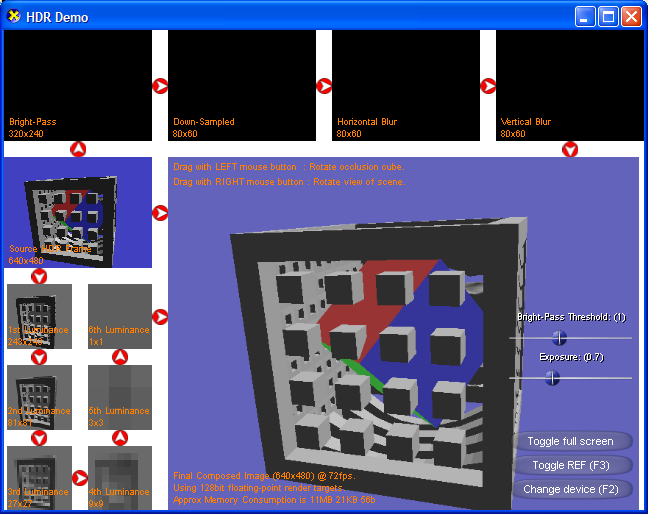
The above image shows a different view of the sample program, this time with no HDR information. Note that the four cells across the top of the image are all black.
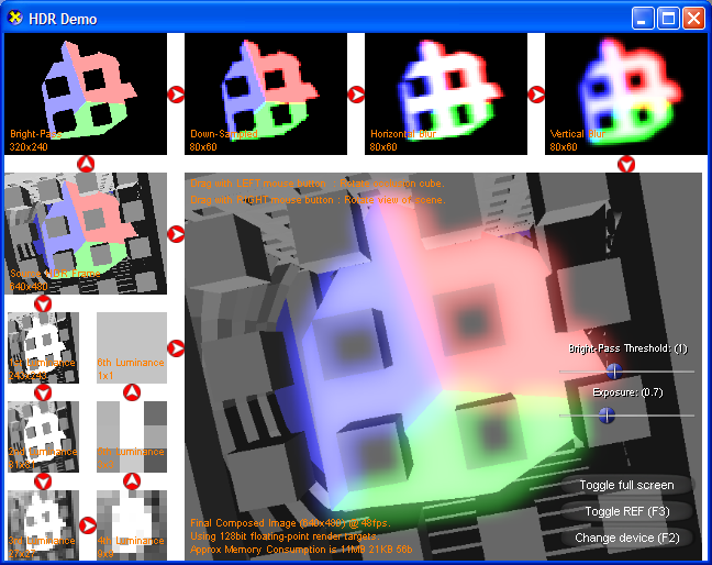
The above image shows a view containing a substantial amount of HDR information. Note that the brighter parts have a slight glow to them (corresponding to the contents of the four cells at the top of the image) and that the background is noticeably darker than the previous image.
The above screenshot show a much more typical scene - one where there is a mixture of normal colours (in the 0.0-1.0 range) and "over bright" HDR values. Because much of the image is relatively dark the luminance mapping is biased towards an exposure to suit a lower range of values. The result is that the few areas of HDR information are over exposed - appearing as white in the final image. Due to the exposure being adapted to the darker source image, the final image is composed such that it's brightness is increased. Because of this the cube and background colour appear much brighter than in the source image.
There are four main stages to a HDR rendering path, all demonstrated by this sample and explained in the following sections:
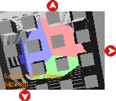
The first step requires that a source image is generated - and is also the simplest step. A floating point render target is used to store values outside of the usual 0.0 to 1.0 (or 0 to 255) range common in traditional Direct3D applications. It is worth comparing the results shown in this cell with the contents of the final image. Exposure adjustments and luminance calculations can make substantial, but subtle, differences. Because the results of this stage will be stored in a high-precision format, any scaling introduced later on in the rendering should produce less noticeable banding or resolution artefacts common with lower-precision rendering.
This sample application uses three faces of the cube at the middle of the scene to produce values greater than 1.0. The remaining three faces are coloured within the normal range, so as to provide some comparison. A better way to produce HDR values in a scene might be to use bright light sources (and associated algorithms).
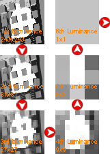
In order to push as much of the work onto the GPU (which is specifically designed to process graphics-related work) a series of down sampling steps are used to compute the overall luminance. Each of the 6 steps reduces the dimensions by a factor of 3 until a 1x1 texture stores a single pixel representing the average luminance across the whole of the source image.
The luminance value is later used to scale the intensity of the final image - a generally bright scene will get darkened and vice versa.

Even with a correct luminance measurement it is quite possible for areas of the image to still be over-exposed. When viewed through a lens (a camera for example) this excess light energy can be subject to reflection/refraction effects. This can result in a slight blurring around the edges of the over-exposed area, an effect that is simulated by the post-processing stage.
This effect is applied to pixels that are greater than or equal to a specific "Bright Pass Threshold". This threshold can be controlled by a slider in the sample's GUI. The first (left-most) cell in the above image shows the initial HDR image with only those pixels that are greater than, or equal to, the bright-pass threshold. A lower threshold will result in more of the initial image being visible in this cell.
In order to blur an image a pixel shader is required to read multiple samples from the source before writing to the destination, and as such can be particularly fill-rate intensive for the GPU. To remedy this performance problem, the first two stages of the post-processing pipeline down sample the input so as to reduce the number of pixels that will be considered by the blurring stages. The final number of pixels submitted to the blurring filter is 1/16th of the initial image.
An advantage of this down-sampling is that when the post-processing results (the right-most cell in the above image) are sampled into the final image, that each pixel covers a larger area meaning that the application can do less work and still achieve noticeable effects. Conversely, aliasing/resolution artefacts can be introduced unless texture filtering is used.
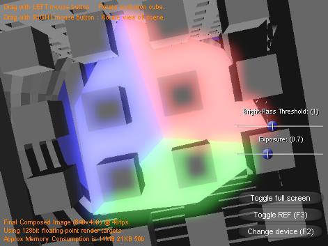
The final image, shown in the bottom right of the screen, takes the results of the aforementioned three stages and computes the correct image. This image will be tone mapped according to the computed luminance, and also include the results of the post-processing blurring around over-exposed elements. Due to the way that the components are additively combined, the bright (over-exposed) areas of the original image appear to "bleed" colour into the properly exposed areas.
It is worth noting that this application was specifically developed as an educational sample - visually demonstrating how the many steps and processes of a HDR rendering path work. Because of this, it hasn't been aggressively optimized for real-time performance.
From a performance perspective there are two interesting aspects to this sample:
Firstly, it is a good example of a GPU bound (and more specifically fill-rate bound) application. The vast majority of the work done on any given frame is offloaded to the GPU. Consequently, performance noticeably reflects the hardware installed. As an experiment, try zooming in/out (mouse scroll wheel) and examining the frame-rate in the bottom-left of the final image. When the scene is suitably zoomed out and covers a small area of the final image the frame rate should be significantly higher than when the scene is zoomed in and covers all of the final image.
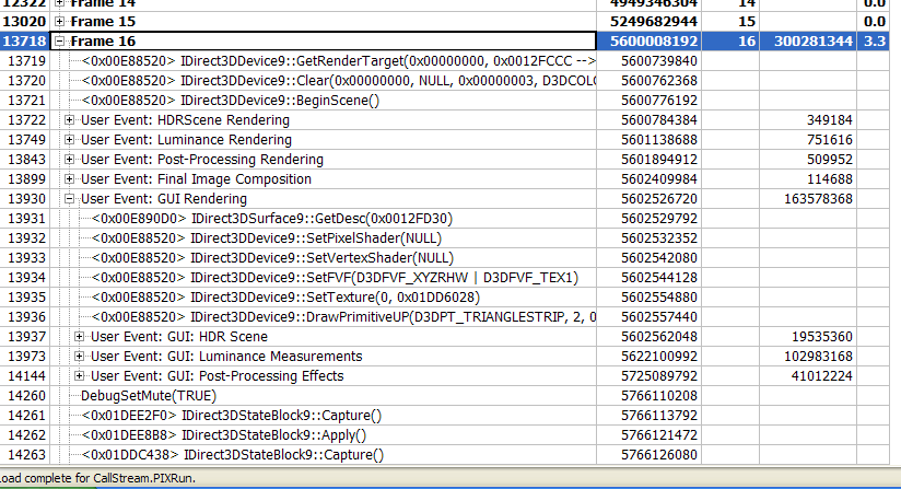
Secondly, the source code for this sample makes particular use of the D3DPERF_BeginEvent() and D3DPERF_EndEvent() API calls. The calls allow PIX for Windows to group related calls together, making the interpretation of call streams a lot more intuitive. Using PIX to record a replayable call-stream capture should yield information similar to the following screenshot - the "User Event" sections are the result of the aforementioned API calls:
