This sample demonstrates one popular shadowing technique called shadow mapping. A shadow map (in the form of a floating-point texture) is written with the scene's depth information with the camera placed at the light's position. Once generated, the shadow map is projected onto the scene during rendering. The depth values in the scene are compared with those in the shadow map. If they do not match for a particular pixel, then that pixel is in shadow. Shadow mapping is a very efficient real-time shadow casting technique.
Note
This sample requires ps_2_0 which supports floating-point textures. On cards that do not support ps_2_0, the sample will revert to a reference device which will degrade performance, but is useful for verifying functionality.

| Source: | (SDK root)\Samples\C++\Direct3D\ShadowMap |
| Executable: | (SDK root)\Samples\C++\Direct3D\Bin\x86 or x64\ShadowMap.exe |
Rendering real-time shadows has been an advanced topic in computer graphics. Shadows enhance the realism of the scene and give better spatial cue to the viewers. The two most common shadow-rendering techniques are shadow volumes and shadow maps. The major advantage of using shadow maps over shadow volumes is efficiency since a shadow map only requires the scene to be rendered twice. There is no geometry-processing needed and no extra mesh to generate and render. An application using shadow maps can therefore maintain good performance regardless of the complexity of the scene.
The concept of shadow mapping is straightforward. First, the scene is rendered to a texture from the light's perspective. This texture is called a shadow map and is generated from specialized vertex and pixel shaders. For each pixel, the pixel shader writes the pixel depth instead of the pixel color. When the scene is rendered, the distance between each pixel and the light is compared to the corresponding depth saved in the shadow map. If they match, then the pixel is not in shadow. If the distance in the shadow map is smaller, the pixel is in shadow, and the shader can update the pixel color accordingly. The most suitable type of light to use with shadow maps is a spotlight since a shadow map is rendered by projecting the scene onto it.
During initialization, the sample creates a texture of the format D3DFMT_R32F to be used for the shadow map. The format is chosen because the shadow map only requires one channel, and 32-bits will provide good precision. Rendering is done in two parts: the first part constructs the shadow map, and the second part renders the scene with shadows.
The shadow map is constructed by rendering the scene with the shadow map texture as the render target. The shaders used for this process are VertShadow and PixShadow. VertShadow transforms the input coordinates to projected light space (the projected coordinates as if the camera is looking out from the light). The vertex shader passes the projected z and w to the pixel shader, as texture coordinates, so that the pixel shader has a unique z and w for each pixel. PixShadow outputs z / w to the render target. This value represents the depth of the pixel in the scene, and has a range from 0 to 1. At the near clip plane, it is 0; at the far clip plane, it is 1. When the rendering completes, the shadow map contains the depth values for each pixel.
The shadowed scene is rendered with two shaders: VertScene and PixScene. VertScene transforms position to projected coordinates and passes the texture coordinates to the pixel shader. In addition, it outputs: the vertex coordinates in view space, the vertex normal in view space, and the vertex coordinates in projected light space. The first two are used for lighting computation. The vertex coordinate in projected light space is the shadow map coordinate. The coordinate is obtained by transforming the world position to light view-space using a view matrix as if the camera is looking out from the light, then transforming the position by the projection matrix for the shadow map.
The pixel shader tests each pixel to see if it is in shadow. First, a pixel is tested to see if it is within the cone of light from the spotlight using the dot product of the light direction and the light-to-pixel vector. If the pixel is within the cone, the shader checks to see if its in shadow. This is done by converting the range of vPosLight (between 0 and 1 to match a texture address range), inverting y (positive y direction is down rather than up when addressing a texture), and then using the coordinate to perform a shadow map look-up.
For each texture lookup, the pixel shader does a 2-by-2 percentage closest filtering (by fetching from each of the four closest texels). For each texel fetched, the texel value is compared to the current pixel depth from the light, or vPosLight.z / vPosLight.w. If the value from the shadow map is smaller, then the pixel is in shadow and the lighting amount for this texel is 0. Otherwise, the lighting amount for this texel is 1. After this is done for all four texels, a bilinear-interpolation is done to calculate the lighting factor for the pixel. The light source will be scaled by this factor to provide the darkening effect of the shadow.
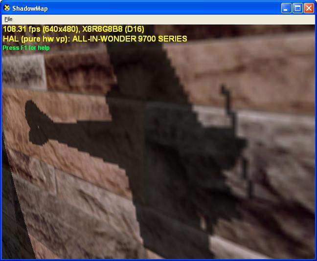
One of the limitations is that the shadows generated with shadow maps do not have sharp edges like some shadows in real life, or shadows generated with shadow volumes. Shadows with shadow maps generally have aliasing near the shadow edges that can be noticeable when viewed close-up, as shown in the figure below. This is an inherent behavior of shadow mapping, because it is an image-based technique. Filtering helps reduce the aliasing, but it cannot completely eliminate the artifact.

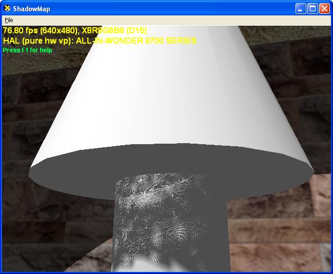
Another type of artifact with shadow maps is caused by the limited precision of depth values. Shadow mapping technique compares two depth values to detect shadows. When the shadow caster and the shadow receiver are close to each other, the limited precision for depth values may not be sufficient to accurately compare the depths of the two objects. Consequently, area that is in shadow may be mistakenly rendered with light, and vice versa, as illustrated in the figure below.

In addition, shadow maps do not work well with point light sources. However, this can be overcome by using a cube texture whose faces form 6 shadow maps around the light source. When constructing the shadow map in this setup, the application first renders the scene 6 times, with each pass rendering depth information onto one face of the cube texture. Then, the scene can be rendered using the cube shadow map.