The D3DLIGHT2 structure defines the light type in calls to methods such as IDirect3DLight::SetLight and IDirect3DLight::GetLight.
For DirectX 5, this structure supersedes the D3DLIGHT structure. D3DLIGHT2 is identical to D3DLIGHT except for the addition of the dwFlags member. In addition, the dvAttenuation members are interpreted differently in D3DLIGHT2 than they were for D3DLIGHT.
typedef struct _D3DLIGHT2 {
DWORD dwSize;
D3DLIGHTTYPE dltType;
D3DCOLORVALUE dcvColor;
D3DVECTOR dvPosition;
D3DVECTOR dvDirection;
D3DVALUE dvRange;
D3DVALUE dvFalloff;
D3DVALUE dvAttenuation0;
D3DVALUE dvAttenuation1;
D3DVALUE dvAttenuation2;
D3DVALUE dvTheta;
D3DVALUE dvPhi;
DWORD dwFlags; // new member for DirectX 5
} D3DLIGHT2, *LPD3DLIGHT2;
Members
dwSize
Size, in bytes, of this structure. You must specify a value for this member. Direct3D uses the specified size to determine whether this is a D3DLIGHT or a D3DLIGHT2 structure.
dltType
Type of the light source. This value is one of the members of the D3DLIGHTTYPE enumerated type.
dcvColor
Color of the light. This member is a D3DCOLORVALUE structure. In ramp mode, the color is converted to a gray scale.
dvPosition
Position of the light in world space. This member has no meaning for directional lights and is ignored in that case.
dvDirection
Direction the light is pointing in world space. This member only has meaning for directional and spotlights. This vector need not be normalized but it should have a non-zero length.
dvRange
Distance beyond which the light has no effect. The maximum allowable value for this member is D3DLIGHT_RANGE_MAX, which is defined as the square root of FLT_MAX. This member does not affect directional lights.
dvFalloff
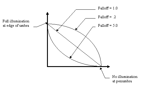
Decrease in illumination between a spotlight's umbra (the angle specified by the dvTheta member) and the outer edge of the penumbra (the angle specified by the dvPhi member). This feature was implemented for DirectX 5.
The intensity of the light at any point in the penumbra is described by the following equation:

In this equation, rho is the angle between the axis of the spotlight and the illuminated point.
A value of 1.0 specifies linear falloff from the umbra to the penumbra. If the value is anything other than 1.0, it is used as an exponent to shape the curve. Values greater than 1.0 cause the light to fall off quickly at first and then fade slowly to the penumbra. Values which are less than 1.0 create the opposite effect. The following graph shows the affect of changing these values:

The effect of falloff on the lighting is subtle. Furthermore, a small performance penalty is incurred by shaping the falloff curve. For these reasons, most developers set this value to 1.0.
dvAttenuation0 through dvAttenuation2
Values specifying how a light's intensity changes over distance. (Attenuation does not affect directional lights.) In the D3DLIGHT2 structure these values are interpreted differently than they were for the D3DLIGHT structure.
The distance from the light to the vertex is normalized to the range by the following formula:
distance = (range-distance)/range
This results in the distance value being from 1.0 at the light to 0.0 at the light's full range. Then the combined intensity factor of the light is calculated using the following formula:
intensity = dvAttenuation0 +
dvAttenuation1 * distance +
dvAttenuation2 * distance squared
This intensity factor is then multiplied by the light color to produce the final intensity of the light.
Setting the attenuation values to 1,0,0 produces a light that doesn't change over distance. Setting the values to 0,1,0 produces a light that is at full intensity at the light, zero intensity at the light's range, and that declines linearly between the two extremes. The values 0,0,1 produce a light that mimics the standard "1/distance squared" falloff rate that should be familiar from introductory physics classes. (The differences in this last case are that the curve is softer and that the intensity of the light doesn't go to infinity at the light source.)
You can use various combinations of values to create unique lights. You can even use negative values ¾ this is another way to achieve a dark light effect. Just as when you use negative values for colors, when you are in ramp mode you cannot use dark lights to produce anything darker than the current setting for the ambient light.
dvTheta
Angle, in radians, of the spotlight's umbra¾that is, the fully illuminated spotlight cone. This value must be less than pi radians.
dvPhi
Angle, in radians, defining the outer edge of the spotlight's penumbra. Points outside this cone are not lit by the spotlight. This value must be between 0 and the value specified for the dvTheta member.
dwFlags
A combination of the following performance-related flags. This member is new for DirectX 5.
| D3DLIGHT_ACTIVE | Enables the light. This flag must be set to enable the light; if it is not set, the light is ignored. |
| D3DLIGHT_NO_SPECULAR | Turns off specular highlights for the light. |
Remarks
In the D3DLIGHT structure, the affects of the attenuation settings were difficult to predict; developers were encouraged to experiment with the settings until they achieved the desired result. For D3DLIGHT2, it is much easier to work with lighting attenuation.
For more information about lights, see Lights and IDirect3DLight.
QuickInfo
Windows NT: Use version 5.0 or later.
Windows: Use Windows 95 or later. Available as a redistributable for Windows 95.
Windows CE: Unsupported.
Header: Declared in d3dcaps.h.
See Also