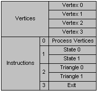
Execute buffers contain a list of vertices followed by stream of instructions about how to use those vertices. All of these are DWORD-aligned.
The following illustration shows the format of execute buffers.

The instruction stream consists of operation codes, or opcodes, and the data that is operated on by those opcodes. The opcodes define how the vertex list should be lit and rendered. Direct3D opcodes are listed in the D3DOPCODE enumerated type. The D3DINSTRUCTION structure describes instructions in an execute buffer; it contains an opcode, the size of each instruction data unit, and a count of the relevant data units that follow.
One of the most common instructions is a triangle list (D3DOP_TRIANGLE), which is simply a list of triangle primitives that reference vertices in the vertex list. Because all the primitives in the instruction stream reference vertices in the vertex list only, it is easy for the transformation module to reject a whole buffer of primitives if its vertices are outside the viewing frustum.
Each execute buffer contains a vertex list followed by an instruction stream. The instruction stream defines how the vertex list should be rendered; it is based on indices into the vertex list.
Although you can choose to use transformed and lit vertices (D3DTLVERTEX), vertices that have only been lit (D3DLVERTEX), or vertices that have been neither transformed nor lit (D3DVERTEX), you can have only one of each type of vertex in a single Direct3DExecuteBuffer object. Some execute buffers are used only to change the state of one or more of the modules in the graphics pipeline; these execute buffers do not have vertices.

For more information about the handling of vertices in execute buffers, see Vertex Types.
The vertex data in an execute buffer is followed by an instruction stream.
Each instruction is represented by:
·An instruction header
·Opcode
·Byte size
·Number of times this opcode is to be repeated
·Byte offset to first instruction
Execute buffer instructions are commands to the driver. Each instruction is identified by an operation code (opcode). All execute data is prefixed by an instruction header. Data accompanies each iteration of each opcode.
Each opcode can have multiple arguments, including multiple triangles or multiple state changes.
There are only a few main instruction types:
·Drawing
·State changes
·Control flow
·Others
The most important of the drawing instructions defines a triangle. In a triangle, vertices are zero-based indices into the vertex list that begins the execute buffer. For more information about triangles, see Triangles.
Other important drawing instructions include line-drawing instructions (D3DLINE) and line-drawing instructions (D3DPOINT).
The system stores the state of each of the modules in the graphics pipeline until the state is overridden by an instruction in an execute buffer.
| Transformation state | World, view and projection matrices |
| Light state | Surface material, fog, ambient lighting |
| Render state | Texture, antialiasing, z-buffering, and so on |
The flow-control instructions allow you to branch on an instruction or to jump to a new position in the execute buffer, skipping or repeating instructions as necessary. This means that you can use the flow-control instructions as a kind of programming language.
The last flow-control instruction in an execute buffer must be D3DOP_EXIT.
Some other execute-buffer instructions do not fall neatly into the other categories. These include:
| Texturing | Download a texture to the device |
| Matrices | Download or multiply a matrix |
| Span, SetState | Advanced control for primitives and rendering states. |