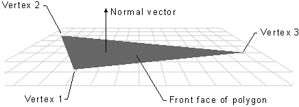
Each face in a mesh has a perpendicular normal vector. The vector's direction is determined by the order in which the vertices are defined and by whether the coordinate system is right- or left-handed. The face normal points away from the front side of the face. In Direct3D, only the front side of a face is visible. A front face is one in which vertices are defined in clockwise order.

Any face that is not a front face is a back face. Direct3D does not always render back faces, therefore back faces are said to be culled. (You can change the culling mode to render back faces, if so desired. See Culling State for more information.)
Direct3D applications do not need to specify face normals; the system calculates them automatically when they are needed. The system uses face normals in the flat shade mode. In Gouraud shade mode, Direct3D uses the vertex normal. It also uses the vertex normal for controlling lighting and texturing effects.
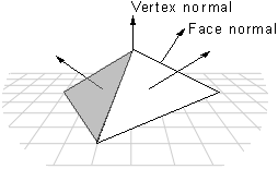
Direct3D applications typically use the D3DVERTEX type for their vertices. The members of the D3DVERTEX structure describe the position and orientation of the vertex. The orientation is indicated by a vertex normal vector. The following code fragment demonstrates how vertex values, including the vertex normal, can be set. The normal vectors are pointing toward the viewport, which is at the origin of the world coordinate system. The vertex positions in this example are specified in world coordinates.
D3DVERTEX lpVertices[3];

// A vertex can be specified one structure member at a time.
lpVertices[0].x = 0;
lpVertices[0].y = 5;
lpVertices[0].z = 5;
lpVertices[0].nx = 0;    // X component of the normal vector.
lpVertices[0].ny = 0;    // Y component of the normal vector.
lpVertices[0].nz = -1;   // Points the normal back at the origin.
lpVertices[0].tu = 0;    // Only used if a texture is being used.
lpVertices[0].tv = 0;    // Only used if a texture is being used.

// Vertices can also by specified on one line of code for each vertex
// by using some of the D3DOVERLOADS macros.
lpVertices[1] = D3DVERTEX(D3DVECTOR(-5,-5,5),D3DVECTOR(0,0,-1),0,0);
lpVertices[2] = D3DVERTEX(D3DVECTOR(5,-5,5),D3DVECTOR(0,0,-1),0,0);
When applying Gouraud shading to a polygon, Direct3D uses the vertex normals to calculate the angle between the light source and the surface. It calculates the color and intensity values for the vertices and interpolates them for every point across all of the primitive's surfaces. Direct3D calculates the light intensity value by using the angle. The greater the angle, the less light is shining on the surface.
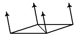
If you are creating an object that is flat, then the vertex normals should be set to point perpendicular to the surface. The following illustration demonstrates this. A flat surface composed of two triangles is defined. The vertex normals all point perpendicular to the surface.
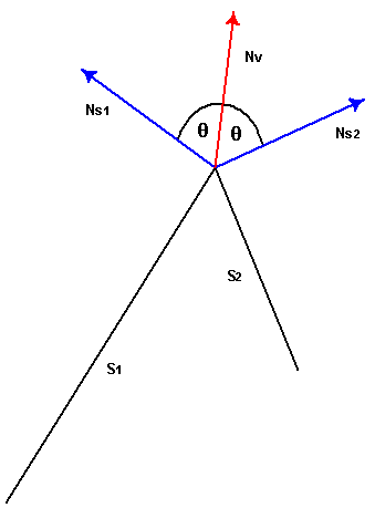
It is more likely, however, that your object is made up of triangle strips, and that the triangles are not coplanar. One simple way to get smooth shading across all of the triangles in the strip is to first calculate the surface normal vector for each polygonal face with which the vertex is associated. The vertex normal can be set to make an equal angle with each of the surface normals. Note, however, that this method may not be efficient enough for complex primitives.
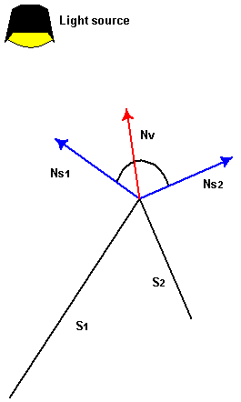
This method is illustrated by the following figure, which shows two surfaces, S1 and S2 seen edge-on from above. The normal vectors for S1 and S2 are shown in blue. The vertex normal vector is shown in red. The angle that the vertex normal vector makes with the surface normal of S1 is the same as the angle between the vertex normal and the surface normal of S2. When these two surfaces are lit and shaded with Gouraud shading, the result will be a smoothly-shaded, smoothly-rounded edge between them.
If the vertex normal leans toward one of the faces with which it is associated, it causes the light intensity to increase or decrease for points on that surface, depending on the angle it makes with the light source. An example is shown in the following figure. Again, these surfaces are seen edge-on. The vertex normal leans toward S1, causing it to have a smaller angle with the light source than it would if the vertex normal had equal angles with the surface normals.
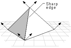
You can use the Gouraud shade mode to display some of the objects in a 3-D scene with sharp edges. If you are using execute buffers, your application needs to duplicate the vertex normal vectors at any intersection of faces where a sharp edge was required, as shown in the following illustration.
If you are using the IDirect3DDevice3::DrawPrimitive or IDirect3DDevice3::DrawIndexedPrimitive methods to render your scene, you must define the object with sharp edges as a triangle list, rather than a triangle strip. When you define an object as a triangle strip, Direct3D treats it as a single polygon composed of multiple triangular faces. Gouraud shading is applied both across each face of the polygon and between adjacent faces. The result is an object that is smoothly shaded from face to face. Since a triangle list is a polygon composed of a series of disjoint triangular faces, Direct3D applies Gouraud shading across each face of the polygon. However it is not applied from face to face. If two or more triangles of a triangle list are adjacent, they appear to have a sharp edge between them.
Another alternative is to change to flat shading mode when rendering objects with sharp edges. This is computationally the most efficient method, but it may result in objects in the scene that are not rendered as realistically as the objects that are Gouraud-shaded.