The strided vertex format contains fields to represent untransformed vertices, lit or unlit, for the IDirect3DDevice7::DrawPrimitiveStrided, IDirect3DDevice7::DrawIndexedPrimitiveStrided, and IDirect3DVertexBuffer7::ProcessVerticesStrided methods. You cannot use the strided vertex format for transformed vertices. Unlike a "normal" vertex, which is a structure that physically contains all the necessary vertex components, a "strided" vertex is a structure that contains pointers to the vertex components rather than the components themselves.
This indirection is accomplished through the D3DDRAWPRIMITIVESTRIDEDDATA structure that is accepted by the DrawPrimitiveStrided, DrawIndexedPrimitiveStrided, and ProcessVerticesStrided methods. You describe strided vertices using the same combinations of flexible vertex format flags as a non-strided vertex. However, unlike non-strided vertices, the flags you use do not indicate the presence of a given field in memory (D3DDRAWPRIMITIVESTRIDEDDATA includes them all), they indicate which the structure members that your application uses. The restrictions for these flags are identical to non-strided vertices, for details, see Flexible Vertex Format Flags.
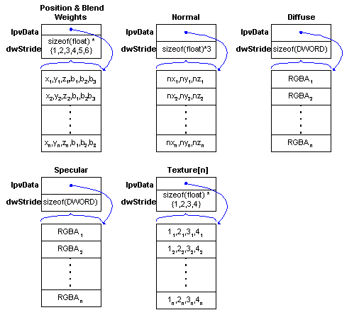
The D3DDRAWPRIMITIVESTRIDEDDATA structure contains 12 D3DDP_PTRSTRIDE structures, one structure each for the position, normal, diffuse color, specular color, and texture coordinate sets for the vertices. Each D3DDP_PTRSTRIDE structure contains a pointer to an array of data, and the stride of that array. These 12 structures provide the indirection that allows your application to arrange vertex components however it needs. For instance, you might use distinct arrays for every vertex component, as shown in the following illustration.

The lpvData member of the corresponding D3DDP_PTRSTRIDE structures contains the address of a buffer that contains an array of vertex components. Each element in each array represents a component for one vertex, which is made up of some number of floats (for position, normal, and texture coordinates) or an RGBA value (for diffuse and specular colors). There is one entry within each array for every vertex to be rendered. The dwStride member of D3DDP_PTRSTRIDE should be set to the memory stride, in bytes, from one entry in the array to the next. The following table describes the components and the corresponding strides for each.
| Component | Stride |
|---|---|
| untransformed position | 3 to 6 floats (x,y,z, plus 0 to 3 blend weights) |
| vertex normal | 3 floats (nx,ny,nz) |
| diffuse color | 1 DWORD (RGBA) |
| specular color | 1 DWORD (RGBA) |
| texture coordinate set | 1, 2, 3, or 4, floats
(1st, 2nd, 3rd, or 4th texture coordinates) |
Note In DirectX 7.0, texture coordinates can be declared in different formats, allowing textures to be addressed using as few as one coordinate, or as many as three texture coordinates (for 2-D projected texture coordinates). For more information, see Texture Coordinate Formats. Use the D3DFVF_TEXCOORDSIZEn set of macros to create bit patterns that identify the texture coordinate formats that your vertex format uses.
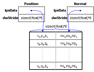
Some developers might choose to include some or all vertex components in an interleaved array. The strided vertex format makes doing this very simple. If your application interleaves the vertex position and normal components, for example, you could visualize the memory layout and corresponding settings in D3DDP_PTRSTRIDE structures as follows.

In this case, the lpvData members of the D3DDP_PTRSTRIDE structures point to two locations within the same buffer, and the strides are set to the combined width of the interleaved components. Of course, you aren't limited to any particular interleaving scheme. So long as you set the data pointers and their strides correctly, any interleaving scheme will work.