Technical Background
The following topics describe some of the technical concepts you need to understand before you write programs that incorporate 3-D graphics. In these sections, you will find a general discussion of coordinate systems and transformations. This is not a discussion of broad architectural details, such as setting up models, lights, and viewing parameters. For more information about these topics, see Direct3D Retained Mode Architecture.
If you are already experienced in producing 3-D graphics, simply scan the following topics for information that is unique to Microsoft® Direct3D® Retained Mode:
3-D Coordinate Systems
There are two varieties of Cartesian coordinate systems in 3-D graphics: left-handed and right-handed. In both coordinate systems, the positive x-axis points to the right and the positive y-axis points up. You can remember which direction the positive z-axis points by pointing the fingers of either your left or right hand in the positive x-direction and curling them into the positive y-direction. The direction your thumb points, either toward or away from you, is the direction the positive z-axis points for that coordinate system.
This section describes the Direct3D coordinate system and coordinate types that your application can use.
Direct3D Coordinate System
Direct3D uses the left-handed coordinate system by default. This means the positive z-axis points away from the viewer, as shown in the following illustration:
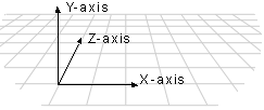
In a left-handed coordinate system, rotations occur clockwise around any axis that is pointed at the viewer.
If you need to work in a right-handed coordinate system—for example, if you are porting an application that relies on right-handedness—you can do so by making two simple changes to the data passed to Direct3D.
Note: Beginning with DirectX version 6.0, you can use IDirect3DRM3::SetOptions to instruct Direct3D Retained Mode to use a right-handed coordinate system. If you use IDirect3DRM3::SetOptions, changing data is not necessary.
Versions of DirectX prior to version 6.0 require the following changes to the data passed to Direct3D Retained Mode to use right-handed coordinates.
- Flip the order of triangle vertices so that the system traverses them clockwise from the front. In other words, if the vertices are v0, v1, v2, pass them to Direct3D as v0, v2, v1.
- Scale the projection matrix by –1 in the z-direction. To do this, flip the signs of the _13, _23, _33, and _43 members of the D3DMATRIX structure.
U- and V-Coordinates
Direct3D also uses texture coordinates. These coordinates (u and v) are used when mapping textures onto an object. The v-vector describes the direction or orientation of the texture and lies along the z-axis. The u-vector (or the up vector) typically lies along the y-axis, with its origin at [0,0,0]. For more information about u- and v-coordinates, see Wraps.
3-D Transformations
In programs that work with 3-D graphics, you can use geometrical transformations to:
- Express the location of an object relative to another object.
- Rotate, shear, and size objects.
- Change viewing positions, directions, and perspective.
You can transform any point into another point by using a 4×4 matrix. In the following example, a matrix is used to reinterpret the point (x, y, z), producing the new point (x', y', z'):

You perform the following operations on (x, y, z) and the matrix to produce the point (x', y', z'):

The most common transformations are translation, rotation, and scaling. You can combine the matrices that produce these effects into a single matrix to calculate several transformations at once. For example, you can build a single matrix to translate and rotate a series of points.
Matrices are specified in row order. For example, the following matrix could be represented by an array:

The array for this matrix would look like the following:
D3DMATRIX scale = {
    D3DVAL(s),    0,            0,            0,
    0,            D3DVAL(s),    D3DVAL(t),    0,
    0,            0,            D3DVAL(s),    D3DVAL(v),
    0,            0,            0,            D3DVAL(1)
};
This section describes the 3-D transformations available to your applications through Direct3D.
Other parts of this documentation also discuss transformations. You can find a general discussion of transformations in the section devoted to viewports in Retained Mode, Transformations. For a discussion of transformations in frames, see Transformations. Although each of these sections discusses Retained Mode API, the architecture and mathematics of the transformations apply to both Retained Mode and Immediate Mode.
Translation
The following transformation translates the point (x, y, z) to a new point (x', y', z'):

Rotation
The transformations described in this section are for left-handed coordinate systems, and so they may be different from transformation matrices you have seen elsewhere.
The following transformation rotates the point (x, y, z) around the x-axis, producing a new point (x', y', z'):

The following transformation rotates the point around the y-axis:

The following transformation rotates the point around the z-axis:

Note that in these example matrices, the Greek letter theta stands for the angle of rotation, specified in radians. Angles are measured clockwise when looking along the rotation axis toward the origin.
Scaling
The following transformation scales the point (x, y, z) by arbitrary values in the x-, y-, and z-directions to a new point (x', y', z'):

Polygons
Three-dimensional objects in Direct3D are made up of meshes. A mesh is a set of faces, each of which is described by a simple polygon. The fundamental polygon type is the triangle. Although Retained Mode applications can specify polygons with more than three vertices, the system translates these into triangles before the objects are rendered. Immediate Mode applications must use triangles.
This section describes how your applications can use Direct3D polygons.
Geometry Requirements
Triangles are the preferred polygon type because they are always convex, and they are always planar—two conditions that are required of polygons by the renderer. A polygon is convex if a line drawn between any two points of the polygon is also inside the polygon.

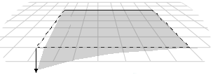
The three vertices of a triangle always describe a plane, but it is easy to accidentally create a nonplanar polygon by adding another vertex.
Face and Vertex Normals
Each face in a mesh has a perpendicular face normal vector whose direction is determined by the order in which the vertices are defined and by whether the coordinate system is right- or left-handed. If the normal vector of a face is oriented toward the viewer, that side of the face is its front. In Direct3D, only the front side of a face is visible, and a front face is one in which vertices are defined in clockwise order.
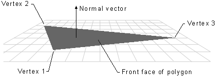
Direct3D applications do not need to specify face normals; the system calculates them automatically when they are needed. The system uses face normals in the flat shade mode. For Phong and Gouraud shade modes, and for controlling lighting and texturing effects, the system uses vertex normals.
Shade Modes
In the flat shade mode, the system duplicates the color of one vertex across all the other faces of the primitive. In the Gouraud and Phong shade modes, vertex normals are used to give a smooth look to a polygonal object. In Gouraud shading, the color and intensity of adjacent vertices is interpolated across the space that separates them. In Phong shading, the system calculates the appropriate shade value for each pixel on a face.
Note Phong shading is not currently supported.
Most applications use Gouraud shading because it allows objects to appear smooth and is computationally efficient. However, Gouraud shading can miss details that Phong shading will not. For example, Gouraud and Phong shading would produce very different results as shown by the following illustration, in which a spotlight is completely contained within a face.
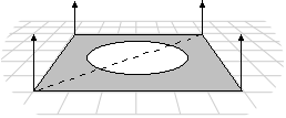
In this case, the Phong shade mode would calculate the value for each pixel and display the spotlight. The Gouraud shade mode, which interpolates between vertices, would miss the spotlight altogether; the face would be rendered as though the spotlight did not exist.
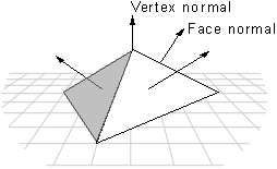
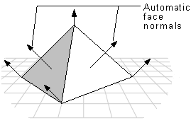
In the flat shade mode, the following pyramid would be displayed with a sharp edge between adjoining faces; the system would generate automatic face normals. In the Gouraud or Phong shade modes, however, shading values would be interpolated across the edge, and the final appearance would be of a curved surface.
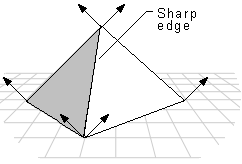
If you want to use the Gouraud or Phong shade mode to display curved surfaces, and you also want to include some objects with sharp edges, your application would need to duplicate the vertex normals at any intersection of faces where a sharp edge was required, as shown in the following illustration.
In addition to allowing a single object to have both curved and flat surfaces, the Gouraud shade mode lights flat surfaces more realistically than the flat shade mode. A face in the flat shade mode is a uniform color, but Gouraud shading allows light to fall across a face correctly. This effect is particularly obvious if there is a nearby point source. Gouraud shading is the preferred shade mode for most Direct3D applications.
Interpolated Triangle Characteristics
The system interpolates the characteristics of a triangle's vertices across the triangle when it renders a face. The following triangle characteristics are interpolated:
- Color
- Specular
- Fog
- Alpha
All of the triangle's interpolated characteristics are modified by the current shade mode:
| Flat | No interpolation is done. Instead, the color of the first vertex in the triangle is applied across the entire face. |
| Gouraud | Linear interpolation is performed between all three vertices. |
| Phong | Vertex parameters are re-evaluated for each pixel in the face, using the current lighting. The Phong shade mode is not currently supported. |
The interpolated color and specular characteristics are treated differently, depending on the color model. In the RGB color model (D3DCOLOR_RGB), the system uses the red, green, and blue color components in the interpolation. In the monochromatic model (D3DCOLOR_MONO), the system uses only the blue component of the vertex color.
For example, if the red component of the color of vertex 1 were 0.8 and the red component of vertex 2 were 0.4, in the Gouraud shade mode and RGB color model the system would use interpolation to assign a red component of 0.6 to the pixel at the midpoint of the line between these vertices.
The alpha component of a color is treated as a separate interpolated characteristic because device drivers can implement transparency in two different ways: by using texture blending or by using stippling.
An application can use the dwShadeCaps member of the D3DPRIMCAPS structure to determine what forms of interpolation the current device driver supports.
Triangle Strips and Fans
You can use triangle strips and triangle fans to specify an entire surface without having to provide all three vertices for each of the triangles. For example, only seven vertices are required to define the following triangle strip.
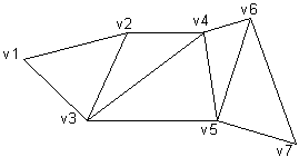
The system uses vertices v1, v2, and v3 to draw the first triangle; v2, v4, and v3 to draw the second triangle; v3, v4, and v5 to draw the third; v4, v6, and v5 to draw the fourth; and so on. Notice that the vertices of the second and fourth triangles are out of order. This is required to make sure that all of the triangles are drawn in a clockwise orientation.
A triangle fan is similar to a triangle strip, except that all of the triangles share one vertex.
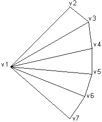
The system uses vertices v1, v2, and v3 to draw the first triangle; v3, v4, and v1 to draw the second triangle; v1, v4, and v5 to draw the third triangle; and so on.
You can use the wFlags member of the D3DTRIANGLE structure to specify the flags that build triangle strips and fans.
Vectors, Vertices, and Quaternions
Throughout Direct3D, vertices describe position and orientation. Each vertex in a primitive is described by a vector that gives its position, a normal vector that gives its orientation, texture coordinates, and a color. (In Retained Mode, the D3DRMVERTEX structure contains these values.)
Quaternions add a fourth element to the [x, y, z] values that define a vector. Quaternions are an alternative to the matrix methods that are typically used for 3-D rotations. A quaternion represents an axis in 3-D space and a rotation around that axis. For example, a quaternion could represent a (1,1,2) axis and a rotation of 1 radian. Quaternions carry valuable information, but their true power comes from the two operations that you can perform on them: composition and interpolation.
Performing composition on quaternions is similar to combining them. The composition of two quaternions is notated as follows:
![]()
The composition of two quaternions applied to a geometry means "rotate the geometry around axis2 by rotation2, then rotate it around axis1 by rotation1." In this case, Q represents a rotation around a single axis that is the result of applying q2, then q1 to the geometry.
Using quaternion interpolation, an application can calculate a smooth and reasonable path from one axis and orientation to another. Therefore, interpolation between q1 and q2 provides a simple way to animate from one orientation to another.
When you use composition and interpolation together, they provide you with a simple way to manipulate a geometry in a manner that appears complex. For example, imagine that you have a geometry that you want to rotate to a given orientation. You know that you want to rotate it r2 degrees around axis2, then rotate it r1 degrees around axis1, but you don't know the final quaternion. By using composition, you could combine the two rotations on the geometry to get a single quaternion that is the result. Then, you could interpolate from the original to the composed quaternion to achieve a smooth transition from one to the other.
Direct3D Retained Mode includes some functions that help you work with quaternions. For example, the D3DRMQuaternionFromRotation function adds a rotation value to a vector that defines an axis of rotation, and returns the result in a quaternion defined by a D3DRMQUATERNION structure. Additionally, the D3DRMQuaternionMultiply function composes quaternions and the D3DRMQuaternionSlerp performs spherical linear interpolation between two quaternions.
Retained Mode applications can use the following functions to simplify the task of working with vectors and quaternions:
Z-Buffers and Overlays
The order in the z-buffer determines the order in which overlays clip each other. Overlays are assumed to be on top of all other screen components. Overlays that do not have a specified z-order behave in unpredictable ways when overlaying the same area on the primary surface. Direct3D Retained Mode does not sort overlays if you do not have a z-buffer. Overlays without a specified z-order are assumed to have a z-order of 0, and will appear in the order they are rendered. The possible z-order of overlays ranges from 0, which is just on top of the primary surface, to 4 billion, which is as close to the viewer as possible. An overlay with a z-order of 2 would obscure an overlay with a z-order of 1. No two overlays can have the same z-order.
 Top of Page
© 1999 Microsoft and/or its suppliers. All rights reserved. Terms of Use.