| Microsoft DirectX 8.1 (C++) |
A flexible vertex format (FVF) code describes the contents of vertices stored interleaved in a single data stream. It generally specifies data to be processed by the fixed function vertex processing pipeline.
Microsoft® Direct3D® applications can define model vertices in several different ways. Support for flexible vertex definitions, also known as flexible vertex formats or flexible vertex format codes, makes it possible for your application to use only the vertex components it needs, eliminating those components that aren't used. By using only the needed vertex components, your application can conserve memory and minimize the processing bandwidth required to render models. You describe how your vertices are formatted by using a combination of Flexible Vertex Format Flags.
The FVF specification includes formats for point size, specified by D3DFVF_PSIZE. This size is expressed in camera space units for non-TL vertices, and in device-space units for TL vertices.
The rendering methods of the IDirect3DDevice8 interface provides C++ applications with methods that accept a combination of these flags, and uses them to determine how to render primitives. Basically, these flags tell the system which vertex components—position, vertex blending weights, normal, colors, the number and format of texture coordinates—your application uses and, indirectly, which parts of the rendering pipeline you want Direct3D to apply to them. In addition, the presence or absence of a particular vertex format flag communicates to the system which vertex component fields are present in memory and which you've omitted.
To determine device limitations, you can query a device for the D3DFVFCAPS_DONOTSTRIPELEMENTS and D3DFVFCAPS_TEXCOORDCOUNTMASK flexible vertex format flags. For more information, see the FVFCaps member of the D3DCAPS8 structure.
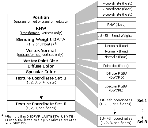
One significant requirement that the system places on how you format your vertices is on the order in which the data appears. The following illustration depicts the required order for all possible vertex components in memory, and their associated data types.

Note Texture coordinates can be declared in different formats, allowing textures to be addressed using as few as one coordinate or as many as four texture coordinates (for 2-D projected texture coordinates). For more information, see Texture Coordinate Formats. Use the D3DFVF_TEXCOORDSIZEn set of macros to create bit patterns that identify the texture coordinate formats that your vertex format uses.
No application will use every component—the reciprocal homogeneous W (RHW) and vertex normal fields are mutually exclusive. Nor will most applications try to use all eight sets of texture coordinates, but Direct3D has this capacity. There are several restrictions on which flags you can use with other flags. For example, you cannot use the D3DFVF_XYZ and D3DFVF_XYZRHW flags together, as this would indicate that your application is describing a vertex's position with both untransformed and transformed vertices.
To use indexed vertex blending, the D3DFVF_LASTBETA_UBYTE4 flag should appear at the end of the FVF. The presence of this flag indicates that the fifth blending weight will be treated as a DWORD instead of float. For more information, see Indexed Vertex Blending.
The following code samples shows the difference between an FVF code that uses the D3DFVF_LASTBETA_UBYTE4 flag and one that doesn't. The FVF defined below does not use the D3DFVF_LASTBETA_UBYTE4 flag. The flag D3DFVF_XYZ3 is present when four blending indices are used because you always use (1 - the sum of the first three) for the fourth.
#define D3DFVF_BLENDVERTEX (D3DFVF_XYZB3|D3DFVF_NORMAL|D3DFVF_TEX1)

struct BLENDVERTEX
{
    D3DXVECTOR3 v;       // Referenced as v0 in the vertex shader
    FLOAT       blend1;  // Referenced as v1.x in the vertex shader
    FLOAT       blend2;  // Referenced as v1.y in the vertex shader
    FLOAT       blend3;  // Referenced as v1.z in the vertex shader
                         // v1.w = 1.0 - (v1.x + v1.y + v1.z)
    D3DXVECTOR3 n;       // Referenced as v3 in the vertex shader
    FLOAT       tu, tv;  // Referenced as v7 in the vertex shader
};
The FVF defined below uses the D3DFVF_LAST_UBYTE4 flag.
#define D3DFVF_BLENDVERTEX (D3DFVF_XYZB4 | D3DFVF_LASTBETA_UBYTE4 |D3DFVF_NORMAL|D3DFVF_TEX1)

struct BLENDVERTEX
{
    D3DXVECTOR3 v;       // Referenced as v0 in the vertex shader
    FLOAT       blend1;  // Referenced as v1.x in the vertex shader
    FLOAT       blend2;  // Referenced as v1.y in the vertex shader
    FLOAT       blend3;  // Referenced as v1.z in the vertex shader
                         // v1.w = 1.0 - (v1.x + v1.y + v1.z)
    DWORD       indices; // Referenced as v2.xyzw in the vertex shader
    D3DXVECTOR3 n;       // Referenced as v3 in the vertex shader
    FLOAT       tu, tv;  // Referenced as v7 in the vertex shader
};
Use the following topics for additional information about the various formats your application can use to declare vertices.