| Microsoft DirectX 8.1 (pixel shader versions 1.0, 1.1, 1.2, 1.3, 1.4) |
Calculates a three-component dot product. The scalar result is replicated to all four channels.
dp3 dest, src0, src1
| Argument | Description | Registers | Version | |||
|---|---|---|---|---|---|---|
| vn | cn | tn | rn | |||
| dest | Destination register | x | 1.0 | |||
| x | x | 1.1, 1.2, 1.3 | ||||
| x | 1.4 | |||||
| src0, src1 | Source register | x | x | x | x | 1.0, 1.1, 1.2, 1.3 |
| x | x | 1.4 phase 1 | ||||
| x | x | x | 1.4 phase 2 | |||
dp3 does not automatically clamp the output result between zero and one. If clamping is necessary, use the saturate modifiers.
dp3 can be co-issued as long as dp3 is writing the color channels and the other instruction is writing the alpha channel.
To learn more about registers, see Registers.
This instruction executes in the vector pipeline, always writing out to the color channels. For version 1.4, this instruction still uses the vector pipeline but may write to any channel.
dp3 r0.rgb, t0, v0 // Copy scalar result to RGB components.
An instruction with a destination register RGB write mask may be co-issued with dp3 as shown below.
dp3 r0.rgb, t0, v0            // Copy scalar result to color components.
+mov r2.a, t0                 // Copy alpha component from t0 in parallel.
The dp3 instruction can be modified using the Signed Scaling input argument modifier (_bx2) applied to its input arguments if they are not already expanded to signed dynamic range. For a lighting shader, the saturate instruction modifier (_sat) is often used to clamp the negative values to black, as shown in the following example.
dp3_sat r0, t0_bx2, v0_bx2 // Here t0 is a bump map, v0 contains the light direction.
This example is for illustration only. The C code accompanying the shader has not been optimized for performance. It can use helper functions from the Sample Framework. The sample framework is the foundation on which many of the samples are built.
This example uses a dot product to square the vertex diffuse color components.

// The shader is shown below.
ps.1.0          // Version instruction.
tex t0          // Declare texture.
dp3 r0, v0, v0  // Dot product squares the vertex color values,
                // color(v0) * color(v0).
                // Bright colors max out at white.
                // Dimmer colors yield gray.
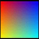
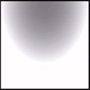
The results of this example are shown below. The input vertex colors are shown on the left. The rendered output from the pixel shader is shown on the right. The left, bottom, and right edges are white because the input color components reach the maximum color value when squared. The center color is gray because the squared color values are lower where the input colors blend together.


Additional code loads a texture in texture stage 0
LPDIRECT3DDEVICE8   m_pd3dDevice;     // Initialize the pointer before using.
LPDIRECT3DTEXTURE8  m_pTexture0;      // Use this variable to hold a pointer to the texture.
TCHAR               strPath[512] = "textureFile.jpg";

D3DUtil_CreateTexture( m_pd3dDevice, strPath, &m_pTexture0, D3DFMT_R5G6B5 );
m_pd3dDevice->SetTexture( 0, m_pTexture0 );