| Microsoft DirectX 8.1 (C++) |
You can control an external device in DirectShow by implementing device control filters. These filters control devices or streams of data that are entirely external to the computer and expose interfaces such as IAMExtDevice, IAMExtTransport, IAMTimecodeGenerator, and IAMTimecodeReader. Generally, external device control filters do not need to expose pins. However, an example of a device control filter that does expose pins might be a filter representing a source of data such as a VCR. A pin-to-pin connection representing the data flowing from the VCR to the capture board enables the device control filter and the video capture filter to communicate with each other and negotiate data types, although they do not use the standard
External devices can include VCRs, video editing stations, audio tape recorders (ATRs), mixers, or any other device used in the video capture and editing process. Capture and editing requires DirectShow external device control filters to provide audio and video synchronization and precise control. You can accomplish synchronization of audio and video during playback, edit, and capture with external clocks or SMPTE timecode.
To understand external device control, it is necessary to understand timecode. The key things to remember about timecode are:
Given this background, two fundamental problems exist with device control. First, hundreds of different communication protocols exist for all the various devices from all the various manufacturers. Although some devices are more widely used than others, such as VCRs and laser disc players, almost all have a different remote control interface. As more sophisticated professional video and audio applications continue to move to the desktop, this problem gets worse. Due to these myriad protocols, you must implement separate DirectShow filters for each external device you want to control.
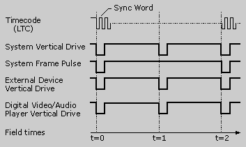
Second, the fundamental problem in the design of professional video and audio systems is that events must occur at precise points in time. Taking a systems view of this issue, consider the following timing diagram.

The horizontal axis denotes time in video fields, or roughly 1/60 of a second for NTSC video. The key point here is that all signals line up in time; that is, timecode starts at the beginning of a frame (System Frame Pulse). External devices, such as tape machines, are aligned with the system reference, as well as digital video playback such as an AVI file run from an AVI-enabled application.
Conformance to this timing requirement is achieved by various means, the most common of which is a master reference signal distributed to all components in the system. This reference is known as blackburst in the video world, so named because it is a composite video signal containing no active video above black level. The "burst" portion of the name refers to the color burst portion of the video signal. Each device connected to the reference must maintain its own synchronization. This means, for example, that a digital video player must switch frames during the vertical blanking interval, a tape machine must switch into record mode during the vertical blanking interval, commands sent to external devices through a serial port must be timed to the frame pulse, and all of these and other synchronized events must occur when the SMPTE timecode hits a predetermined value. Failure to conform to these rules results in
Accomplishing all this in the professional video world is relatively straightforward, but in the hybrid world of desktop video, it is very difficult.
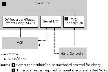
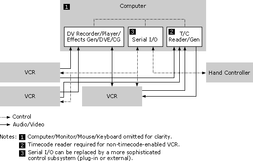
Building on the concepts presented so far, the two design examples in the following diagrams illustrate a potential configuration of external devices.


The block diagrams show that it is relatively simple to distribute the reference signal to all of the boxes. For example, to deal with synchronization that takes place within the computer between the timecode reader and digital video player, it is recommended that either a "vertical drive" hardware interrupt, specialized operating system services, or some other custom solution be used.
Finally, if you intend to write a filter that controls an external device, you should implement the IAMExtDevice and IAMExtTransport interfaces. If your filter reads or generates timecode, you should also implement IAMTimecodeReader, IAMTimecodeGenerator, and IAMTimecodeDisplay interfaces provided by DirectShow. Additionally, if you need to move binary messages to and from an external device—for example, to download executable code for the external device's microprocessor to execute—you should do this by implementing the COM IDataObject interface, which has a complete set of methods for handling binary data transfers. Use this interface for whatever custom data transfer purposes your filter needs.