Each cursor-resource file contains one cursor image for each image identified in the cursor directory. A cursor image consists of a cursor-image header, a color table, an XOR mask, and an AND mask. The cursor image has the following form:
BITMAPINFOHEADERcrHeader; RGBQUAD crColors[]; BYTE crXOR[]; BYTE crAND[];
The cursor hot spot is a single pixel in the cursor bitmap that Windows uses to track the cursor. The crXHotspot and crYHotspot members specify the x- and y-coordinates of the cursor hot spot. These coordinates are 16-bit integers.
The cursor-image header, defined as a BITMAPINFOHEADER structure, specifies the dimensions and color format of the cursor bitmap. Only the biSize through biBitCount members and the biSizeImage member are used. The biHeight member specifies the combined height of the XOR and AND masks for the cursor. This value is twice the height of the XOR mask. The biPlanes and biBitCount members must be 1. All other members (such as biCompression and biClrImportant) must be set to zero.
The color table, defined as an array of RGBQUAD structures, specifies the colors used in the XOR mask. For a cursor image, the table contains exactly two structures, since the biBitCount member in the cursor-image header is always 1.
The XOR mask, immediately following the color table, is an array of BYTE values representing consecutive rows of a bitmap. The bitmap defines the basic shape and color of the cursor image. As with the bitmap bits in a bitmap file, the bitmap data in a cursor-resource file is organized in scan lines, with each byte representing one or more pixels, as defined by the color format. For more information about these bitmap bits, see Section 1.1, “Bitmap-File Formats.”
The AND mask, immediately following the XOR mask, is an array of BYTE values representing a monochrome bitmap with the same width and height as the XOR mask. The array is organized in scan lines, with each byte representing 8 pixels.
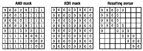
When Windows draws a cursor, it uses the AND and XOR masks to combine the cursor image with the pixels already on the display surface. Windows first applies the AND mask by using a bitwise AND operation; this preserves or removes existing pixel color. Window then applies the XOR mask by using a bitwise XOR operation. This sets the final color for each pixel.
The following illustration shows the XOR and the AND masks that create a cursor (measuring 8 pixels by 8 pixels) in the form of an arrow:

Following are the bit-mask values necessary to produce black, white, inverted, and transparent results:
| Pixel result | AND mask | XOR mask |
| Black | 0 | 0 |
| White | 0 | 1 |
| Transparent | 1 | 0 |
| Inverted | 1 | 1 |