GDI classifies six of the mapping modes as constrained mapping modes. These mapping modes are constrained because the scaling factor is fixed, so an application cannot change the number of logical units that Windows maps to a physical unit. The relationship of logical units to physical units for each constrained mapping mode follows:
| Mapping mode | Logical units | Physical unit |
| MM_HIENGLISH | 1000 | 1 inch |
| MM_HIMETRIC | 100 | 1 millimeter |
| MM_LOENGLISH | 100 | 1 inch |
| MM_LOMETRIC | 10 | 1 millimeter |
| MM_TEXT | 1 | Device pixel |
| MM_TWIPS | 1440 | 1 inch |
Note:
The MM_HIENGLISH, MM_HIMETRIC, MM_LOENGLISH, MM_LOMETRIC, and MM_TWIPS mapping modes sometimes map logical units to device units in ways that do not correspond exactly to the preceding table. This typically occurs on displays; for example, on an VGA display there is a 33 percent increase in the dimensions of the device units.
The increase in the dimensions of device units occurs so that the same output looks equally crisp and readable whatever the device resolution and the display technology for the device. An application can use the GetDeviceCaps function with the LOGPIXELSX and LOGPIXELSY indices to discover the scaling factor.
In each of the six constrained modes, one logical unit is mapped to a predefined physical unit. For instance, the MM_TEXT mapping mode maps one logical unit to one device pixel, and the MM_LOENGLISH mapping mode maps one logical unit to 0.01 inch on the device. Examples for these two modes follow.
The default mapping mode is MM_TEXT. In this mapping mode, one logical unit is mapped to one pixel on the device or display.
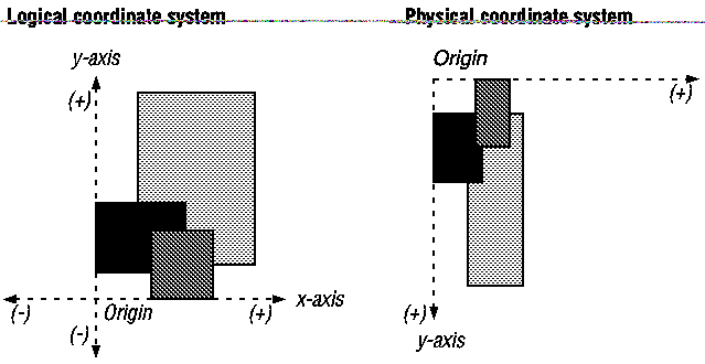
The following illustration shows three rectangles created by a Windows application by using the MM_TEXT mapping mode. The drawing on the left illustrates the logical coordinate space, and the one on the right illustrates the device, or physical, coordinate space. The rectangles appear vertically elongated in the physical space because pixels on the chosen display are longer than they are wide. The rectangles appear to be upside-down because the positive y-axis extends downward in the physical-coordinate system.

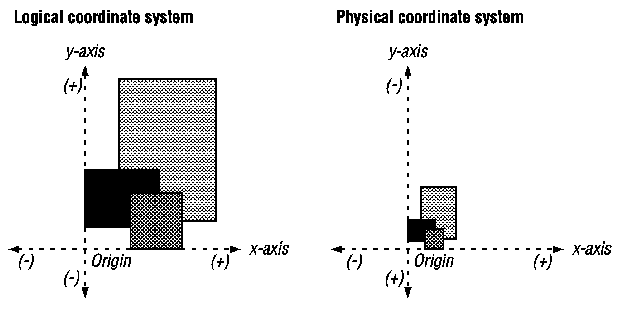
The following illustration shows three rectangles created by a Windows application by using the MM_LOENGLISH mapping mode. The drawing on the left illustrates how the rectangles appear in relation to the x-axis and y-axis in the logical coordinate system. The one on the right illustrates how the rectangles appear in relation to the x-axis and y-axis in the physical coordinate system.
