

Index
Topic Contents
Previous Topic: Quality-Control Management
Next Topic: Improving Capture Performance
 |
 | 
|

|
| |||
| |||
About Capture Filter Graphs
This article provides a brief introduction to capture and introduces the fundamentals of filter graphs that provide video or audio capture or preview capabilities. It includes conceptual diagrams of the most common capture-related filter graphs to help you visualize the components in each filter graph and see how they fit together. It discusses the role of particular filters such as video and audio capture filters, the AVI MUX (multiplexer) filter, and the file writer filter. It also highlights unusual points such as filters (for audio capture in this case) that have input pins.
See Where Can I Learn About... for a list of topics relating to capture, including articles that discuss writing code to perform capture.
If you are new to DirectShow, read Filter Graph Manager and Filter Graphs and Filters and Pins to familiarize yourself with the architecture's fundamental concepts.
Contents of this article:
Capture Introduction
Video and audio capture enable you to take multimedia data from an external source such as a VCR or camera, and view it, listen to it, or save it on your computer's hard drive. Your computer must include video or audio capture hardware to perform capture. For audio capture, a sound card with a microphone or line-in jack is usually sufficient. Some video capture cards support audio capture as well, so you might not need two separate cards. The DirectShow architecture provides default components (filters) that enable you to capture video and audio data streams given the appropriate capture hardware and drivers. DirectShow takes advantage of new capture drivers that are written as DirectShow filters and also uses existing Video for Windows-style drivers.
Video and Audio Capture Filter Graphs
Typical filter graphs that provide video and audio capture and video preview capability must include video capture, audio capture, multiplexer (MUX), file writer, and video renderer filters. If you need a subset of these features your filter graph can be simpler and contain fewer filters. This section begins by discussing the simpler capture filter graphs and the components they contain. It then discusses filter graphs that combine features and build upon the basic capture filter graphs to provide more functionality.
This section contains the following topics:
- Video Preview Filter Graphs
- Video Capture Filter Graphs
- Video Capture and Preview Filter Graphs Combined
- Adding Audio Capture
- Capture Filter Input Pins
- Example Capture Filter Graph
Video Preview Filter Graphs
A video preview filter graph enables you to watch the video on your computer screen as it plays from your VCR, camera, or other video source. The video preview filter graph is very simple. It contains a video capture filter and a video renderer. The capture filter provides the video data from the capture card, exposing a pin called Preview to which the video renderer connects. The video renderer provides a playback window in which it displays the video data. If the capture filter produces compressed data, you must insert a decompressor filter between the capture filter and the renderer.
Note Capture filters are not required to expose a preview pin.
The portion of the graph from the preview pin downstream to and including the video renderer is called the preview section of the filter graph.
DirectShow provides video capture and video renderer filters. If you have an existing Video for Windows-style capture driver, the video capture filter wraps the functionality provided by that driver so that it works with the DirectShow architecture. You can also write your own video capture filter or use third-party capture filters.
The following diagram illustrates a simple video preview filter graph.

Video capture filters expose a pin for capture as well as an optional pin for preview. Pin names can vary from those shown in the diagram above. The next section of this article discusses the capture pin.
Note Some capture filters have a capture pin and do not have a preview pin. If the capture pin is the only pin on a capture filter, connect the renderer to the capture pin.
Video Capture Filter Graphs
A video capture filter graph takes captured video data and saves it to a file. The term "video capture filter graph" often encompasses video capture and preview functionality, but this section uses the term in the strict "capture to file" sense.
The simplest video capture filter graphs contain a video capture filter, multiplexer filter, and file writer filter. The capture filter provides video data from the capture card, just as it does in video preview filter graphs. It exposes a pin for capture to which the multiplexer filter (MUX) connects. The multiplexer filter understands a particular file format, such as audio-video interleaved (AVI). It has multiple input pins and one output pin. Each input pin takes in a stream of audio or video data. The MUX combines the separate streams of data into the appropriate file format and then passes the newly combined data through its output pin to the file writer. The file writer filter writes the data stream from the MUX to disk without any knowledge of the particular data format.
The MUX and file writer work together as a unit.
DirectShow provides the AVI MUX and File Writer filters. The AVI MUX filter packages data streams into an AVI file stream; therefore, the File Writer always writes files in AVI format if it is connected to the AVI MUX.
The following diagram illustrates a simple video capture filter graph.
Video Capture and Preview Filter Graphs Combined
A filter graph that provides both video capture and video preview capabilities combines all the filters from video capture and video preview filter graphs. All the filters serve the same role as in the smaller filter graphs.
The following diagram illustrates the combined video capture and video preview filter graph.
Adding Audio Capture
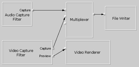
None of the filter graphs discussed thus far capture audio data. As a result, they produce movies that are silent upon playback. Adding an audio capture filter to the video capture and preview filter graph, as illustrated in the following diagram, provides the missing audio capture capability.

Audio capture filters accept audio data from the audio capture card much as video capture filters accept video data. A capture card might provide both video and audio capture capabilities, so the corresponding video and audio capture filters might process data from the same capture card. If your system contains separate audio and video capture cards, the video capture and audio capture filters process data from separate capture cards.
Audio capture filters also expose a capture pin that connects to the multiplexer filter in the same way that the capture pin on a video capture filter connects to the multiplexer. The multiplexer's role becomes more important in this filter graph because it has more than one connected input pin. Each connected input on the MUX provides a separate data stream (one video and one audio in this case), which the MUX combines into its supported file format, and the file writer saves the resulting data to a file on disk.
Capture Filter Input Pins
An unusual feature of audio and video capture filters is that they can expose input pins, unlike other source filters. Source filters do not typically expose input pins because they are the source of the data. They typically pass data on to the next filter in the graph rather than accepting input data from another filter. The input pins provide a mechanism to access input characteristics. Audio capture filters support the IAMAudioInputMixer interface to provide access to such characteristics as recording and bass levels on each input line. Each input pin represents an input line such as microphone, CD audio, or MIDI on the audio card.
The following diagram shows a full-featured filter graph that provides video preview, and video and audio capture. The audio capture filter exposes an input pin for each input line on the capture card. Internally, each pin supports IAMAudioInputMixer to enable applications to access input characteristics on each line.
Example Capture Filter Graph
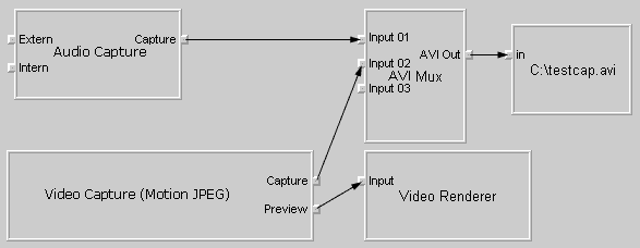
Now that you're familiar with capture filter graphs in general, here's a screen shot of a capture filter graph from the Filter Graph Editor tool that is included with the DirectShow SDK. It builds upon the conceptual diagrams examined earlier.

The preceding screen shot shows a motion JPEG video capture filter and an audio capture filter in a capture filter graph. Both filters process data from the same capture card because the capture card happens to capture both video and audio data streams. A computer might include a sound card in addition to a capture card, giving you a choice between two audio sources and therefore between audio capture filters to insert in the capture filter graph.
The screen shot is very similar to the conceptual diagrams examined earlier with the exception of filter names and input pin names. The input pins on the audio capture filter are labeled Intern and Extern. The file writer filter saves captured video and audio data to a file called Testcap.avi at the root of the C: drive.
If you have capture hardware installed on your system and use the Filter Graph Editor tool to create a capture filter graph, it will appear similar to the preceding screen shot. The names of the video and audio capture filters depend on the capture drivers installed on the computer. If present, the audio capture filter's input pins might have different names from those illustrated. The name of the file to which captured data is saved will differ as well. The preview pin will connect to a decoder if the data from the pin is compressed, and the decoder will then connect to the renderer.
© 1998 Microsoft Corporation. All rights reserved. Terms of Use.