

Index
Topic Contents
Previous Topic: Data Flow in the Filter Graph
Next Topic: Controlling Filter Graphs Using Visual Basic
 |
 | 
|

|
| |||
| |||
Constructing Filter Graphs Using Visual Basic
This article describes how to use ActiveMovie Control type library objects to manage the components of a filter graph — filters and pins — in applications based on Microsoft® Visual Basic®, version 5.x. It also describes the functionality demonstrated by the Builder sample application. This article is written for the Visual Basic developer who is already familiar with application programming in Microsoft Windows®, Windows-based multimedia programming, and Automation features of the Visual Basic programming system.
Contents of this article:
- About Filter Graphs
- About the DirectShow Quartz.dll Objects
- Creating a Filter Graph
- Generating the Complete Filter Graph
- Creating a New Filter Graph and Adding Filters
- Connecting Filter Pins
- Viewing Pin Connection Information
- Creating a Custom Graph
- Summary
About Filter Graphs
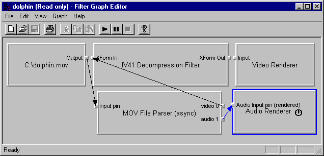
The Filter Graph Editor provided with the Microsoft DirectShow™ Software Development Kit (SDK) is a graphical tool that creates and manages filter graphs. There are three types of filters: source filters, transform filters, and renderer filters. The Filter Graph Editor is a graphic user interface you use to construct filter graphs by inserting filters and creating connections between them. For example, you can render the filter graph for a specific multimedia source file, such as Dolphin.mov, and see each of the connections in the graph, as in the following example.

The same filter graph objects, filters and pins, can be managed from a sample Visual Basic-based application that uses Quartz.dll. For simplicity, the Visual Basic-based application uses list boxes rather than graphical elements to show the parts of the filter graph, and displays information for only one filter and only one pin at a time. (The purpose of the application is not to compete with the Filter Graph Editor, but to demonstrate how to retrieve and manage the same underlying filter graph information using Visual Basic.)
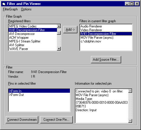
The following illustration shows the same multimedia source file, Dolphin.mov, as depicted by the Visual Basic-based sample application.

The list box labeled "Filters in current filter graph" lists the four filters required for this source file. The list box labeled "Pins in selected filter" lists the two pins defined for the selected Indeo Video R4.1 Decompression Filter: the "XForm In" and "XForm Out" pins. The XForm In pin is selected, so the application displays detailed information about this pin, including its direction and connection information.
The remainder of this article discusses the Visual Basic code you can use to retrieve and manage such filter graph information. In addition to the general-purpose code that works with any source input, the application includes a routine that illustrates a more likely use of these properties and methods—building a specific hard-coded filter graph for your Visual Basic-based application.
This article assumes you have already set up your Visual Basic environment to use Quartz.dll. For more information about setting up your Visual Basic environment, see Controlling Filter Graphs Using Visual Basic.
About the DirectShow Quartz.dll Objects
Quartz.dll provides objects that you can use in your Visual Basic-based applications to manage filters and pins. There is an implicit hierarchy among these objects; that is, you must often access the properties of one object to obtain another object. In the following example, an object that appears indented below another indicates that you obtain that lower-level object from a property or method of the higher-level object.
Filter graph object (IMediaControl)
  Filter collection (RegFilterCollection, FilterCollection properties)
    Filter Info object (IFilterInfo or IRegFilterInfo in filter collection)
      Pin collection (Pins property)
        Pin Info object (IPinInfo item in pins collection)
The top-level object in the hierarchy is the filter graph object, or the IMediaControl object, which represents the entire filter graph. You can access two properties of the IMediaControl object to obtain collections of filter objects. The RegFilterCollection property represents the filters registered with the system. The FilterCollection property represents the filters that are part of the filter graph.
As with other collections accessible to Visual Basic, you can access individual items in the collections by using the Visual Basic for each...next statement. The number of items in the collection is indicated by the Count property of the collection.
The filter collection contains IFilterInfo objects. Each IFilterInfo object has a Pins property that represents a collection of pins defined for that filter.
The pins collection contains IPinInfo objects. Each IPinInfo object includes detailed information about that pin, including its media type and its connection to another pin.
To examine a specific pin on a filter in the filter graph, use the following procedure.
- Obtain the filter graph object.
- Use the IMediaControl.FilterCollection property of the filter graph object to obtain the collection of filters present in the filter graph.
- Search through the filter collection for the specific filter.
- Use the IFilterInfo.Pins property of the filter object to obtain the collection of pins defined for the filter.
- Search through the pins collection for the specific pin.
- Examine the properties of the pin object to find connection information and other information for the pin.
Creating a Filter Graph
There are three distinct ways to use Quartz.dll to create a filter graph; each way offers a different amount of control over the filter graph. These range from automatically generating the entire filter graph to specifying every filter and pin connection. The three approaches are as follows:
- Automatic.
Generate the complete filter graph from either a multimedia source or a stored filter graph file.
- Semi-automatic.
Create a new (empty) filter graph, add one or more filters, then automatically generate all filters and connections needed to render a specific pin.
- Manual.
Create a new (empty) filter graph, add individual filters to the graph, and explicitly add connections between pins.
The sample application, Builder, demonstrates all three approaches. The application's "Generate from input file" command on the FilterGraph menu supports the first approach. The New command (empty) on the FilterGraph menu supports the other two approaches.
Generating the Complete Filter Graph
The following code fragment demonstrates how to generate the complete filter graph based on the multimedia source or stored filter graph. After creating an IMediaControl object that is initially "empty," the application calls the IMediaControl.RenderFile method to build up the complete graph:
' fragment from the Filter Graph menu's Generate from input file command
    ' start by creating a new, empty filter graph;
    Dim g_objMC as IMediaControl  ' from the General Declarations section
    ...
    Set g_objMC = New FilgraphManager  ' create the new filter graph
    ' ...
    ' Use the common File Open dialog to let the user select the input file
    CommonDialog1.ShowOpen  ' user selects a source or filter graph
    ' call IMediaControl.RenderFile to add all filters and connect all pins
    g_objMC.RenderFile CommonDialog1.filename  ' generates the complete graph
Creating a New Filter Graph and Adding Filters
The following code fragment demonstrates how to create the new (empty) filter graph object.
' fragment from the Filter Graph menu's New (empty) command handler
    Dim g_objMC as IMediaControl  ' from the General Declarations section
    ...
    Set g_objMC = New FilgraphManager  ' create the new filter graph
When you choose to create an empty filter graph and add individual filters, you must know the filter type. In general, there are three categories of filters: source filters, transform filters, and renderer filters. The procedure for adding source filters uses a different method than the procedure for adding transform and renderer filters.
Add source filters to the filter graph by calling the IMediaControl.AddSourceFilter method and supplying the name of a file of the specified source type or stored filter graph.
The main form of the application includes a button labeled "Add Source Filter..." that uses the common File Open dialog box to query the user for the name of the source file or stored filter graph. The application supplies the specified file as the parameter to AddSourceFilter.
Dim objFilter As Object  ' temporary object for valid syntax; not used

    CommonDialog1.ShowOpen  ' get the name of the source or filter graph file
    g_objMC.AddSourceFilter CommonDialog1.filename, objFilter
Add transform and renderer filters to the filter graph by calling the IRegFilterInfo.Filter method. The IRegFilterInfo object can be obtained from the IMediaControl.RegFilterCollection property, which represents the collection of filter objects registered with the system and available for use.
After creating the filter graph and obtaining the IMediaControl object, use the following procedure to add filters.
- Obtain the list of registered filters by getting the IMediaControl.RegFilterCollection property.
- Search through the collection for the desired filter. Each element in the collection is an IRegFilterInfo object.
- Add the filter to the filter graph by calling the IRegFilterInfo.Filter method.
In the sample program, the list box labeled "Registered filters" contains the names of all the filters that appear in the RegFilterCollection property. The following code fragment illustrates steps 1 and 2 in the previous procedure.
 ' code fragment that populates the registered filter list box
' global variable g_objRegFilters is set to IMediaControl.RegFilterCollection
' Set g_objRegFilters = g_objMC.RegFilterCollection
Dim filter As IRegFilterInfo
    listRegFilters.Clear
    If Not g_objRegFilters Is Nothing Then
        For Each filter In g_objRegFilters  ' for each filter in collection
            listRegFilters.AddItem filter.Name ' add name to the list box
        Next filter
    End If
The sample application contains an Add button that adds the selected registered filter to the current filter graph. The following code fragment illustrates step 3 in the previous procedure.
' code fragment from the event handler for the "Add" button
Dim filter As IRegFilterInfo
' find the selected filter and add it to the graph
' g_objRegFilters is the IMediaControl object RegFilterCollection property
For Each filter In g_objRegFilters
    If filter.Name = listRegFilters.Text Then  ' the selected filter?
        Dim f As IFilterInfo  ' yes
        filter.filter f  ' add to the filter graph, return IFilterInfo f
        If f.IsFileSource Then
            CommonDialog1.ShowOpen
            f.filename = CommonDialog1.filename
        End If
        Exit For
    End If
Next filter
Connecting Filter Pins
After adding individual filters to the filter graph, you can establish connections between the filters by explicitly connecting each pin, or by automatically generating all connections that are needed downstream from a specific pin.
In both cases, you must traverse the hierarchy of DirectShow objects to obtain the IPinInfo object that represents a pin of the filter object. This involves finding the desired filter in the filter collection of the filter graph object, then finding the desired pin in the pin collection of the filter object.
Listing Filters in the Filter Graph
All filters in the filter graph are available in a collection that you can access using the IMediaControl.FilterCollection property.
When the user adds a filter to the filter graph, the application refreshes the list of current filters by using the IMediaControl.FilterCollection property, as shown in the following code fragment.
' refresh the list box that contains the current filters in the graph
    listFilters.Clear
    For Each objFI In g_objMC.FilterCollection
        listFilters.AddItem objFI.Name ' add to list box
    Next objFI
Listing Pins Defined for a Filter
You can access the pins defined for a filter object through the IFilterInfo.Pins property. The Pins property is a collection of individual IPinInfo objects.
After you obtain an individual IPinInfo object from the collection, you can access its properties and call its methods, as shown in the following code fragment.
For Each objPin In g_objSelFilter.Pins
    If objPin.Name = listPins.Text Then  ' selected pin?
        Set g_objSelPin = objPin ' yes, update information
        ' ... perform operations using that pin
    End If
Next objPin
After you have obtained the pin object, you can explicitly connect to one other pin or automatically generate all subsequent pin connections needed to render the pin.
Explicitly Connecting Two Pins
The IPinInfo object provides three methods to connect pins: Connect, ConnectDirect, and ConnectWithType. Connect adds other transform filters as needed, ConnectDirect does not add transform filters, and ConnectWithType performs the connection only if the specified pin matches the specified media type.
The sample application connects two pins using the IPinInfo.Connect method, as shown in the following code fragment. You can call the Connect method from either of the two pins that are to be connected.
' The sample application displays another form to select the second pin
' or "other pin" that is to be connected to this pin.
    frmSelectPin.OtherDir = g_objSelPin.Direction
    Set frmSelectPin.Graph = g_objMC  ' give that form a copy of the graph
    Set frmSelectPin.SelFilter = g_objSelFilter  ' and the current filter
    frmSelectPin.RefreshFilters  ' display available filters to connect
    frmSelectPin.Show 1  ' display the form
    If frmSelectPin.bOK Then ' user has selected one--used OK button
        Dim objPI As IPinInfo
        Set objPI = frmSelectPin.SelPin ' get the new pin from the form
        g_objSelPin.Connect objPI  ' connect the two pins
        RefreshFilters  ' display the latest pin information
    End If
Automatically Connecting Pins
Call the IPinInfo.Render method to automatically generate all portions of the filter graph that are needed downstream from that pin.
The term downstream refers to all connections needed to construct a complete path from that pin to a renderer filter. For example, consider the representation of the filter graph by the Filter Graph Editor, which shows connections as moving from the source filter at the left to the renderer filter at the right. The Render method adds all required filters and connections to the right of the specified pin.
The application includes a Connect Downstream command button. The code that handles this command automatically establishes all pin connections downstream from the specified pin object, as shown in the following code fragment.
' call IPinInfo.Render
' complete the graph downstream from this pin
' g_objSelPin refers to the pin selected in the list box labeled 'Pins'
    g_objSelPin.Render
Viewing Pin Connection Information
When you have obtained a pin object from the collection available from the IFilterInfo.Pins property of the filter object, you can list its connection and other information.
The sample application uses the IPinInfo.ConnectedTo property to obtain the pin object to which it is connected, as shown in the following code fragment.
' Add detailed pin information to the text box on the right
' when the user clicks on a pin in the list box on the left
  Dim strTemp As String
  On Error Resume Next
  Dim objPin As IPinInfo
  For Each objPin In g_objSelFilter.Pins
    If objPin.Name = listPins.Text Then ' selected in list box?
      Set g_objSelPin = objPin  'yes, get all information
      strTemp = ""  ' clear existing displayed pin information
      Dim objPinOther As IPinInfo
      Set objPinOther = objPin.ConnectedTo
      If Err.Number = 0 Then  ' yes, there is a connection
        strTemp = "Connected to pin: " + objPinOther.Name + " "
        Dim objPeer As IFilterInfo
        Set objPeer = objPinOther.FilterInfo
        strTemp = strTemp + " on filter: " + objPeer.Name + " "
        Dim objMTI As IMediaTypeInfo
        Set objMTI = objPin.ConnectionMediaType
        strTemp = strTemp + vbCrLf + "Media Type: " + objMTI.Type
      End If
      If objPin.Direction = 0 Then
        strTemp = strTemp + " " + vbCrLf + "Direction: Input"
      Else
        strTemp = strTemp + " " + vbCrLf + "Direction: Output"
      End If
    txtPinInfo.Text = strTemp
    End If
  Next objPin
Creating a Custom Graph
The sample application featured in this article is similar to the filter graph editor utility, allowing a user to create and manage any filter graph. Most applications will not provide such a general-purpose interface—they are more likely to create only the specific filter graphs needed by the application.
The sample application provides one subroutine that creates such a custom filter graph. The Options menu offers a "Build custom graph" command that calls this subroutine.
The routine that handles this command creates five filter objects and eight pin objects. The routine then connects pins by calling the IPinInfo.Connect method.
The graph connects the following filters: AVI Source, AVI Decompressor, AVI Splitter, Video Renderer, and Audio Renderer. These filters can be connected by reusing just two pin object variables. For clarity, however, each pin object is defined using a name that indicates its position in the filter graph.
The filters and pins are declared as follows:
Dim pSourceFilter As IFilterInfo  ' AVI Source Filter; has two pins
Dim SourceOutputPin As IPinInfo  'Source Filter output pin

Dim pAVISplitter As IFilterInfo ' AVI Splitter
Dim SplitterInPin As IPinInfo   ' AVI Splitter pin "Input"
Dim SplitterOut00Pin As IPinInfo  ' AVI Splitter pin "Stream 00"
Dim SplitterOut01Pin As IPinInfo  ' AVI Splitter pin "Stream 01"

Dim pDECFilter As IFilterInfo  ' AVI Decompressor; has two pins
Dim DECInPin As IPinInfo   'AVI Decompressor pin "XForm In"
Dim DECOutPin As IPinInfo   ' AVI Decompressor pin "XForm Out"

Dim pVidRenderer As IFilterInfo ' Video Renderer, has one pin
Dim VidRendInPin As IPinInfo  ' Video Renderer pin "Input"

Dim pAudioRenderer As IFilterInfo 'Audio Renderer, has one pin
Dim AudioRendInPin As IPinInfo ' Audio Renderer pin "Input"
The application adds the source filter object by calling the IMediaControl.AddSourceFilter method:
' create the source filter using IMediaControl.AddSourceFilter
    CommonDialog1.ShowOpen  ' get the name of the source AVI file
    g_objMC.AddSourceFilter CommonDialog1.filename, pSourceFilter
The application adds the other filter objects by searching for a specific name in the registered filter collection (the filter collection is available from the IMediaControl.RegFilterCollection property), and calling the IRegFilterInfo.Filter method when it finds the specific filter to add:
' add all non-source filters from the collection of registered filters
    Set g_objRegFilters = g_objMC.RegFilterCollection
' use the local subroutine AddFilter to find the filter named
' "AVI Decompressor" in the collection, and set the variable pDECFilter
    AddFilter "AVI Decompressor", pDECFilter
The AddFilter subroutine of the application loops through all the filters present in the collection. When the names match, it calls the IRegFilterInfo.Filter method to add the filter to the filter graph:
Private Sub AddFilter(FName As String, f As IFilterInfo)
' call IRegFilterInfo.Filter

    Set LocalRegFilters = g_objMC.RegFilterCollection
    Dim filter As IRegFilterInfo
    For Each filter In LocalRegFilters
        If filter.Name = FName Then
            filter.filter f
            Exit For
        End If
    Next filter
The application calls similar code for the AVI Compressor, AVI Splitter, Video Renderer, and Audio Renderer filters. After obtaining all the filter objects, the application uses the IFilterInfo.Pins property to find specific pin objects. The code loops through all pin objects in the collection, searching for the specific pin names and setting the individual pin objects when they are found, as shown in the following code fragment.
' Get the source filter pin we need to build the graph
For Each pPin In pSourceFilter.Pins
      Debug.Print pPin.Name
      If pPin.Name = "Output" Then
          Set SourceOutputPin = pPin
      End If
    Next pPin

'Add DEC filter
    AddFilter "AVI Decompressor", pDECFilter
    'Print out list of pins on decompressor filter
    For Each pPin In pDECFilter.Pins
      Debug.Print pPin.Name
      ' save specific pins to connect them
      If pPin.Name = "XForm In" Then
          Set DECInPin = pPin
      End If
      If pPin.Name = "XForm Out" Then
          Set DECOutPin = pPin
      End If
    Next pPin

'Add AVI Splitter
    AddFilter "AVI Splitter", pAVISplitter
    'Print out list of pins on decompressor filter
    For Each pPin In pAVISplitter.Pins
      Debug.Print pPin.Name
      ' save specific pins to connect them
      ' pin 0, pin 1
      If pPin.Name = "input pin" Then
          Set SplitterInPin = pPin
      ElseIf pPin.Name = "Stream 00" Then
          Set SplitterOut00Pin = pPin
      ElseIf pPin.Name = "Stream 01" Then
          Set SplitterOut01Pin = pPin
      End If
    Next pPin
After initializing the eight pin objects, it is a simple matter to call the IPinInfo.Connect method to establish the four connections between them. The following code fragment demonstrates the connection calls.
' connect the pins
' Note:  error handling omitted for brevity
'Connect Source video output pin to AVI splitter input pin
    SourceOutputPin.Connect SplitterInPin
' Connect AVI splitter stream 00 to AVI decompressor
    SplitterOut00Pin.Connect DECInPin
' Connect AVI splitter stream 01 to audio renderer
    SplitterOut01Pin.Connect AudioRendInPin
 'Connect AVI decompressor output pin to Video renderer input pin
    DECOutPin.Connect VidRendInPin
You can establish the connection from either pin; after a successful call to the Connect method, you can access the connection information from either pin object.
Summary
In summary, this article discussed the use of the following DirectShow objects, properties, and methods.
Task DirectShow properties or methods Create a new, empty filter graph. Set objMediaControl = New FilgraphManager. Generate the complete filter graph for a specific file. Call the IMediaControl.RenderFile method. Add a source filter. Call the IMediaControl.AddSourceFilter method. Add a renderer or transform filter. Get the IRegFilterInfo objects using the IMediaControl.RegFilterCollection property; call the IRegFilterInfo.Filter method. List the pins of a filter object. Get the IPinInfo objects using the IFilterInfo.Pins property. Explicitly connect two pins. Call the IPinInfo.Connect method. Create all connections from the pin to the renderer filter. Call the IPinInfo.Render method. © 1998 Microsoft Corporation. All rights reserved. Terms of Use.