Norman Judah
Architectural Consultant, Microsoft Consulting Services
Abstract
In designing a cooperative-processing application, the application designer must address what components of the application are candidates for distribution and determine the criteria for distribution. An application model is provided to aid the designer in developing cooperative-processing applications. The model addresses the problem of functional decomposition beyond the traditional methodologies. The next major hurdle is how to operate and manage the distributed application. Several proposals are put forward to enrich the architecture by integrating distributed-application management.
Many application designers are currently being confronted with the question of how to design a "client-server" or "cooperative-processing" application. In many cases, this also entails a redesign of a monolithic application currently in production: the downsizing scenario. Client-server architecture provides the opportunity to optimize network resources and increase developer productivity. However, implementation at the application design level lacks an application architecture and a methodology to assist the designer and provide a degree of rigor and consistency to the design process. This technical article proposes an application architecture, an application design model, and a rudimentary methodology for functional decomposition.
All of the architectural recommendations and rules are not meant to be axiomatic, but are intended to provide a guideline on how to proceed with this analysis. Each situation must be considered on a case-by-case basis.
The application designer must first determine what components of the application are candidates for distribution and what are the criteria for distribution. The application model is provided to aid the designer in developing cooperative-processing applications. It addresses the problem of functional decomposition beyond the traditional methodologies.
An application model is a set of guidelines provided to the application developer community. The application model extends beyond the architecture, to include organizational issues, application management, testing, and so on.
The model consists of a toolbox of APIs, standards, style guides, and sample applications with which developers can design, build, and operate cooperative-processing applications. A toolbox that is enforced organizationally provides a consistent API style, thereby reducing investment and protecting the long-term investment. It also means that common functions can be migrated over time into a core set of functions supported by the architecture.
An API-based model allows you to share both code segments from a copy library and executing modules. Many traditional mainframe systems have, for example, both interactive and batch versions of applications for inventory management. Changes to the order-processing system typically imply changes to both batch and interactive applications. Both interactive and batch processes could share the same server process, even within one machine, thereby reducing maintenance. An alternate scenario could be different client environments interfacing to a single server process, for example, a Microsoft® Windows™-based PC workstation and a UNIX® workstation sharing a mainframe customer database.
Another example is the transparent migration of a corporate database to an alternate location, technology, or data model. The migration is considered to be transparent when there is little or no impact on the other components of the application outside of those that directly communicate to the data server. Typical configuration could be migration from dBASE® to Microsoft SQL Server or IMS/DB to DB2. This methodology for isolation of the database technology is not new, and has been utilized for some time by forward-thinking developers. What is proposed in this new architecture is an API–based model across multiple layers in an application, and not limited to the data server.
The application model is then extended further by developing a methodology for functional decomposition. Current methodologies propose a decomposition to the elementary business process. The proposed methodology decomposes the elementary business process one step further into elementary systems processes. This decomposition then facilitates the identification of cooperative-processing pairs, typically associated with external data objects and associated actions. (See the subsection "A Methodology for Application Design" for the definition of cooperative-processing pair.)
Cooperative processing is the decomposition of an application into fragments, which can be distributed across several nodes in a logical network. These fragments then execute cooperatively to deliver the application function. These fragments can be viewed as encapsulated objects, where each object could be composed of both process and data.
"Client-server" is but one instance of the cooperative-processing model; another is "peer-to-peer."
An application architecture is a set of infrastructure components, methodologies, and procedures within which the application developer must create business solutions. It also provides a rigorous framework for consistent analysis and development.
The architecture and its APIs isolate the application and provide platform independence, location independence, and communication protocol independence. The implication is that it is the responsibility of the system programmer to provide these key components of the architecture, and that the application programmer can proceed with the task at hand, working with business partners providing a competitive advantage.
Having decomposed the application into its elementary system processes, and identified the cooperative-processing pairs, the designer can now optimize the utilization of network resources and decide on the functional distribution of the application.
The application topology is the description of the location in a network of each of the elementary systems processes determined from the functional decomposition of an elementary business process. (See "A Methodology for Application Design" for definitions of elementary business process and elementary systems process.)
Outside of the actual application development, there are two additional major components that must be integrated into the application architecture from its genesis:
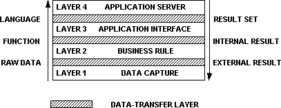
The proposed four-layer application model is a model for segmenting the business application, in order to identify candidates for distribution. With respect to the open systems interconnect (OSI) reference model for network protocols, this analysis falls within the application layer.
The four-layer model is characterized by:
Each one of the layers can be isolated and defined according to the above characterization. Figure 1 defines the generic versions of the layers.

Figure 1. A four-layer model, characterized by data flow between layers
The application model followed by traditional application developers is the "COBOL blob": a single, very large, monolithic program performing one or more business functions. Some developers realized the benefits of modularizing the code with respect to the criteria outlined above, and there are examples of the data-capture layer being isolated. Several tools have appeared on the market allowing the data-capture layer to become distinct, for example, Telon® and Case:W® (see Figure 2).

Figure 2. The traditional development model
The data-transfer layer is the glue that links all the other application layers. It exists between all layers in the hierarchy. This is by no means a null layer, and it contains significant functionality, but all of it is at the system level, not the application level. What defines each instance of the data-transfer layer is the calling and called APIs into and out of the layer.
The data-transfer layer provides the location and protocol independence to the application developer. Named pipes is an example of an API that provides protocol independence, but it still requires the pipe name to be qualified by the server name. To provide location independence to the application, while using named pipes, the data-transfer layer must determine the remote server location. Figure 3 shows that the actual communication protocol is buried within the data-transfer layer, and that the external APIs do not change when different communication protocols are implemented.
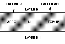
Figure 3. A portable data-transfer layer
Another conclusion is that if the server is relocated to an alternate technology (and perhaps communication protocol), the application client does not change. However, the data-transfer layer needs to have the knowledge that an alternate protocol should be used. It is also significant to note that the Null protocol is a valid protocol within the data-transfer layer. This facilitates, for example, the development and testing of both client and server components within the same node, and then the relocation of each component to its production location.
Another example of functionality provided by the data-transfer layer is data conversion when the adjacent application layers run in different technologies, for example, text conversion from ASCII to EBCDC between a PC and a mainframe, or conversion of a floating point number between Intel and Motorola microprocessor-based systems.
This is the layer that is the only point of contact with the end user, be it a person or a process. An example of a data-capture process could be a bar code scanner used for inventory management, possibly at a point-of-sale terminal. The data can be acquired either through manual entry using a key pad, or by passing the UPC label over a scanner. The primary function of this layer is to acquire the data from the external interface and convert it into a format for internal consumption. Similarly, on the output side, the internal data are converted into external representation.
The data-capture and presentation layer has the following characteristics:
Consistent Layer 1-Layer 2 Data-Transfer Specification isolates the data-capture layer and permits transparent substitution of front-end interfaces. A typical example is a SQL-based transaction processing application that was originally developed on a mainframe using a 3270-style interface. As mentioned in an earlier example, there may be a concurrent batch interface to the same transaction. The first steps in downsizing are typically a redesign of the front-end, providing a graphical user interface (GUI). Using the proposed model, the investment in the other three layers of the code should be protected through the transition to the new interface.
Another example could be the bar code scanner mentioned above, where the data-capture layer provides bar code and communication protocol isolation. There are several bar code standards in various industries. The application logic should not require knowledge of the bar code type to proceed with the business logic. This factor would be isolated within the data-capture layer. What this also means is that adding another bar code style or interface standard (for example, bit or byte protocols) would not affect the application code, and all changes can be contained within the data-capture layer.
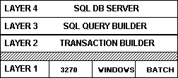
Figure 4. Alternate data-capture layers without modification to other layers
The business-rule layer is the first migration into a business context. This layer maps each object/action pair to an application function. There exists a list of actions (application transactions) that are functionally oriented service requests (for example, Add Customer, Update Order, and so on). The actions selected through the data-capture layer are then mapped to this list of possible actions and associated application functions. This is not limited to transaction processing type applications, but, for example, the selected action could be an ad-hoc query against a sales database.
The business-rule layer has the following characteristics:
In the case of Microsoft SQL Server, this is the stored-procedure interface.
The application-interface layer converts from the purely functional to server-specific into the language of the server. For example, the business process of "add new customer" is translated into a series of SQL statements that operate on a relational database.
The application-interface layer has the following characteristics:
The application-server layer is the actual server process itself. This may be a product such as Microsoft SQL Server, or may be a custom-developed server. Another example is the X-12 interface for an EDI application. This layer is the only layer where there are any standards in the public domain either already established or currently under development.
The application-server layer has the following characteristics:
Interprocess communication is not a new technology. Traditional methods for interprocess communication between two local processes in the same machine include, for example, passing parameters via shared local work areas or common data pools (Figure 5).

Figure 5. The traditional interprocess communication methods
The major advance in the technology is the capability to support interprocess communication across multiple nodes in a network. For the application developer this is the great leap of faith—remote data transfer, where the individual tasks are unaware of the partner process being local or remote. The data-transfer layer provides this transparency and is cognizant of data types and conversion to the internal data formats for each hardware platform. For example, floating point numbers have different representation in the Intel® x86 and IBM® System 3090 architectures.
Previous generations of remote data transfer had to deal with the node synchronization issues as a customized implementation within the application. The synchronization problems deal with the availability of the partner system, loss of the partner during the transaction, graceful recovery, and so on, and the presentation of message failures in a reliable, predictable manner to both partners' processes, where possible.
High-level protocols such as named pipes and TCP/IP sockets have enabled reliable, remote data transfer. There is a higher level API that is also emerging called the remote procedure call (RPC). The RPC hides from the client process the fact that the server may be on another node, and the calling protocol from the client is the same as if the called procedure were local; in effect preserving the paradigm of the application programmer to that of calling a local procedure.

Figure 6. Remote interprocess communication
There are numerous possibilities for segmenting an application and distributing the functionality across several nodes in the network. In the following analysis, examples are given for segmenting the application at each layer.
The simplest example of functional distribution is using remote front-end data-capture and presentation services, such as remote presentation system, X-Windows server, or the bar code reader on a point-of-sale terminal.

Figure 7. Distributed data-capture and presentation layer
This method of segmentation shows significant opportunity for economic benefit; the functionality is distributed to the appropriate platform to facilitate optimization of network resources. There are numerous examples of this interface style:

Figure 8. The client-server model
Many organizations have been faced with the problem of migrating corporate data to a new database technology, with the desire to protect their existing investment. There are in fact three major activities: migrate the application to the new database, bridge the data from the old to the new database, and finally, retire the old database. Using a modular design as in Figure 9, the simple addition of the DB2 Driver would facilitate the migration from IMS/DB to DB2. The significant issue is that the application code in the business-rule layer has no knowledge of the internals of the data server or the business data model. (In the example below IMS is a networked database and DB2 is relational.) One potential benefit is that the front-end application can operate on either database, and the data can potentially be migrated at a later date.

Figure 9. Tactical model for database migration
Another example of a client-server application is the shared application server that is unaware of heterogeneous clients using different protocols.
A configuration seen in many manufacturing companies is a VAX-based manufacturing resource planning (MRP) system supervising the manufacturing process. The MRP system is a server to two distinct client systems. The company also has an IBM Multiple Virtual System (MVS)–based order-processing system feeding transactions to the MRP system. Similarly, there is a UNIX-based engineering workstation used to download engineering computer-aided design (CAD) data to the manufacturing system. In this case, both the mainframe and the workstation are clients to the MRP server.
It is interesting to note that the mainframe can, in fact, perform as a client in a network, rather than being limited exclusively to a server role. The general role of a mainframe should be as a peer node in the network, with the capability of being both a client and a server, rather than being restricted to just a server.
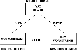
Figure 10. Shared application server with a mainframe client
Most of the application servers currently available conform to the class of functional distribution shown in Figure 11. Typically, they would be database servers, both relational and nonrelational, file servers, print servers, communication servers, and so on. However, there is a class of servers that has a semantic interface, a language that defines the external functionality of the server. For example:
It is interesting to note that this interface layer currently has several standards published by vendors and standards organizations. In the case of a relational database, the actual interface could likely be a SQL dialect, depending on the technology vendor. However, groups like the SQL Access Group are working on an industry standard to ensure that SQL clients can interoperate across different servers.

Figure 11. Distributed application servers
All the previous examples have included only two active nodes in any application. The four-layer model is, however, valid for multiple nodes. A typical example is the application gateway shown in Figure 12. Consider a portable notebook PC-based application used by sales representatives on the road. After a day's work, each sales representative dials into the mainframe to download the orders of the day. In most cases, there is an existing mainframe application to support this function and a HLLAPI interface is used in the notebook to upload the orders. (HLLAPI is the high-level language API specified by IBM as an API to the LU2 3270 data stream. It is frequently used to provide a new front-end interface to existing mainframe applications that cannot be modified.) Each notebook must now support asynchronous dial-in access for 3270 protocols as well as the HLLAPI.
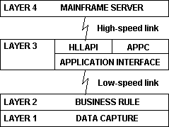
Figure 12. Three-tiered architecture with an application gateway
Over time, the mainframe is upgraded to support advanced program-to-program communication (APPC), and each and every notebook must be upgraded to support not only the new application code but APPC as well. This represents a formidable challenge in a notebook with only asynchronous communication support. (APPC is an API verb set specified by IBM as an application API to the LU6.2 data stream.)
An alternate strategy is to use a three-tiered architecture, with an application server as the middle tier. This server does not necessarily need to be a database server. In the example above, the remote notebooks communicate with the application gateway at the functional level between the business-rule and application-interface layers. In this example, the low-speed interface could be using the named pipes interface. The proposed architecture also potentially reduces data flow and hence improves response time. The application gateway isolates the remote clients from the server protocol and technology changes. The API migration from HLLAPI to APPC could be implemented with changes isolated to the mainframe and the application gateway, while the notebook remains unaffected, outside of possible improved performance.
Information engineering methodologies recommend that all business functions be decomposed to the elementary business process. This is a process that leaves the database in a consistent state before and after execution; that is, the data in the database represent a consistent view of the state of the business.
This concept has been extended by introducing a new entity, the elementary systems process. Each elementary business process can be decomposed into up to four elementary systems processes, each corresponding to one layer in the four-layer application model proposed previously.
Each elementary business process is a candidate for distribution, within the architecture. It is not mandatory to force the decomposition to four elementary systems processes; the decomposition should be appropriate to the application. For example, if SQL Server stored procedures have been standardized as the corporate style for database queries, then it might be appropriate to only model that split. Thus, all possible database queries can be defined and installed as SQL Server objects. However, to be able to gain long-term benefits from the model, the decomposition should be completed to all four levels and the code modularized accordingly.
An elementary systems process is one of the decomposed child processes from a parent elementary business process. It is also a candidate for distribution on the network. An elementary business process is self-contained and independent of other processes. In contrast, the elementary systems process cannot execute in isolation and is dependent on other elementary systems processes to complete an elementary business process.
The traditional process hierarchy diagram or functional decomposition diagram can simply be extended by one generation to provide a diagrammatic representation of this decomposition. The concept can then be taken one step further to fully specify the external interface of each elementary business process.
The four-layer application model is characterized by the data flowing across the interface between the layers. This would typically be a function identifier, parameter set, and a returning result set. The function identifier can be either explicit (for example, remote procedure call) or implicit (for example, execute SQL query). This is the identification of external data objects and associated actions, or in object-oriented design terms, the method and the associated message. The extended process hierarchy diagram in Figure 13 can then be extended one step further by drawing the data flows between the elementary processes. In data modeling terms, the data flow can be specified as a series of import and export views.
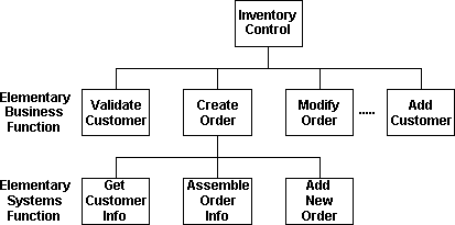
Figure 13. An extended process hierarchy diagram
Further analysis is then required to identify candidates for distribution and the cooperative-processing pair. A cooperative-processing pair is a pair of elementary systems processes that interface directly with one another, either remotely or locally. An elementary business process can be composed of one or more cooperative-processing pairs.
The examples shown in Figures 13 and 14 depict a typical order entry application. The "create order" elementary business process has been decomposed into three elementary systems processes, corresponding to layers one through three of the model. Layer four, the application server, has been omitted for simplicity. It would typically be a relational database with an SQL interface. The information views between the layers can be identified and depicted graphically as shown in Figure 14. These views should be a complete definition of the data that passes across the interface. In the above example, the order profile could contain a variable length component that specifies the product code and quantity for each item in the order. The order profile also contains a fixed length component, being the customer account profile (customer name, customer number, and so on).
The data-capture layer and the "get-customer-and-product-information" process obtain order profile and customer and product data. These data are then passed to the business-rule layer, "assemble order information." At this point, the business context is now entered; in this case, a new order is entered. Therefore, the import view into the application-interface layer, "add new order," contains both the data in the order and the service specification to add a new order. The application-interface layer would then build the actual SQL query and issue the database update. The data moving back down the layers in this case is simply the validation of the update, until it is presented to the end user in the data-capture layer.
Distributed application management is neither network management nor asset management. Both these technologies are concerned with the management of physical entities—nodes in a network, printers, communication paths, and so on. There is, however, a void in the marketplace in the area of managing and operating the logical components of an application that is running on more than one node, that is, the processes in an application. Application management is not only a set of tools, but also an organizational commitment.
In most organizations, the "Help Desk" is a clerical function where the actual call from the end user is logged and directed to another group for problem resolution. In many cases, the problem is passed from group to group without resolution, and rarely with any feedback to the client. Cooperative-processing applications will aggravate this situation, primarily because the problem determination has been compounded and the skill set to determine the actual problem has also been increased.
There is a need to define new roles and responsibilities for the first-line support organization. There are four distinct groups that could be enlisted in the support of a cooperative-processing application (Figure 15):

Figure 15. Roles for distributed application management and operation
The real problem associated with the call to Help Desk is that "My computer does not work!" can lie in any of the above four areas. The introduction of cooperative-processing applications is an opportunity to define new roles and responsibilities within the support organization with a single focus. This new group would be the focal point for any problem from the field relating to the application and its environment, rather than just the application. The staff within the group should be cross-trained in all areas, and have the skill, abilities, and training to determine the cause of the problem. The problem may be resolved within the group, but may also be passed to other groups. In this case, though, the receiving group has some degree of confidence that the problem has been sufficiently researched and that there is a high probability that the problem is in their area. This structure removes the barrage of calls to the current organizations that are user-related errors. This new central group would be composed of highly skilled individuals and would require a major commitment by the organization.
The following model is an example of how distributed application management can be implemented. It is not intended to be a complete specification, nor is it a product; it is intended more as a means to identify the requirements and issues that need to be considered by the system designer.
Application management must be integrated into the architecture and the data transfer layers, as an integral component of the infrastructure (Figure 16). Retrofitting the hooks into an existing toolset can be extremely disruptive. If it is impossible to provide all the functionality initially, as a bare minimum, the APIs should be defined and the hooks implemented into the core code. This will minimize the disruption when the functionality is added.
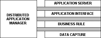
Figure 16. Application management integrated into the architecture
A typical example of the role of distributed application management is for graceful shutdown and restart of a distributed application, across multiple nodes.
Distributed application management infrastructure
A local distributed application management agent (DAMA) must be loaded into every node that will participate in the management activity. The DAMA is the focus in every node for management activity. There is a need to communicate between agents in different nodes and the distributed application manager (DAM), which could be running in any node in the network. The manager communicates to the agents via a series of service requests:
Local agents may not communicate directly with one another for the purposes of application management. This activity is not to be confused with the concept of a network resource broker that locates processes or resources on the network. This activity could be performed by the local agent.
An example of a common service that the DAMA could provide is a unified, common API set to explicitly log events from the application and also implicitly log transactions and events from within the data-transfer layer.
Application monitoring and control
This is the core function of the distributed application manager (DAM): the ability to monitor and control processes remotely across the network. It is not the monitoring of the status of the node, but the status of the processes within the node. The DAM should, for example, be able to:
Performance monitoring and statistics
On demand, the DAMA should be able to track the following type of statistics for capacity analysis, for example:
These statistics could be used for capacity-monitoring purposes, to detect when the application and/or network topologies or equipment profiles should be modified to accommodate future demand for network and application resources.
Message tracing and debugging
To aid in the problem analysis, debugging, and monitoring of distributed applications across heterogeneous systems, a full message trace and debug facility must be provided. This facility will then integrate into the testing environment described in the subheading "Integrated Application Testing Environment." Integrating this capability into the infrastructure relieves each application developer from having to develop this capability in each individual application, probably in incompatible implementations. The tracing facility should have minimal performance impact on active processes, and be dynamically enabled and disabled. This capability should include, but not be limited to, the following:
In any distributed application environment, there is always the possibility of having multiple versions of the client and server software active in the network. Multiple version support is more than the physical movement of files within the network. It includes, but is not limited to, the procedures necessary to provide the following:
Again, support for multiple versions must be integrated into the base application environment. An additional tool can be utilized to facilitate the remote distribution of application modules and system software. It should be noted that the physical transfer of the new files is one component of release management; it includes the repository of files, procedures to update the repository from the application development environment, a database of versions that are active in each node, and so on.
In following the rigor of the four-layer model, the data moving across the interfaces can be well defined, and can also be depicted diagrammatically, as shown in Figure 15. Because the process may be distributed across physical nodes, the data moving into and out of the data-transfer layers can also specify the data moving between nodes in the network. For any given application, the contents of the message packets can be specified, given knowledge of the data, to these behaviors that form the functional specification for the client-server interface, at the data-transfer layer.
Therefore, for a particular application, or even a transaction, a meta-data description of the packets could be specified at the detailed design stage, even prior to actually building the system. This meta-data description should reproduce the packets as if they were recorded on the network using the actual application. The meta-data can, however, be extended to support the expected results as well; a predefined set of request and response packets can be defined in each case. An integrated testing environment would generate the test packets and validate the result set in each case. The meta-data description can be used as the definitive test specification for each cooperative-processing pair.
There is much to be gained from integrating the test environment into the application architecture, the most significant benefit being that the application test specification can be (and should be) built at the same time as the application functional specification. The test specification then becomes integrated into the application source code and is preserved and updated with the source when the functionality is enhanced. Because the application architecture is a rigorous, complete specification, the testing environment and all its component pieces can be well defined and could be delivered as part of the architecture. All applications could use this common utility with predictable behaviors.
There are numerous case studies available to demonstrate the appropriate segmentation of an application in a business context; two are outlined below. The first deals with an installation with many different client machines requesting services. The second example is for a sales representative in the field requiring what once was mainframe data access.
There are many organizations that have a very large installed base of PC workstations, either stand-alone or networked to some degree. Many of these machines are AT-class machines with limited memory and processing capability. It is very difficult to identify all the possible servers these clients might wish to address. If each server has its own programming interface, then the addition of a new server implies the addition of the APIs for that server into every possible client. This could easily result in the client being overloaded, but a more significant problem is the software distribution that must be kept current.
Now the four-layer model can be applied to this application. The traditional model might have been to provide all the server APIs in the client, thereby making the split at the application server (level 3-4). The messages between nodes specify a service code and a set of parameters, and the clients must have some knowledge of the servers, such as the ability to connect to and disconnect from each server.
An alternative is to make the split at the application interface (layer 2-3). The messages between nodes also contain the service specifier, indicating which application server to use. The client does not connect directly to the application server, and does not have a direct relationship with the server, nor does the client require the server API to be resident in the client node. The client code can be very compact, since all the server-specific code is resident in another node. New services can easily be added to the client, without affecting any existing application, simply by expanding a table of allowable services and service codes.
Application security can easily be added into the server (Security Manager in Figure 17), and the actual connections to the clients can be maintained independently of the application servers themselves, if appropriate.

Figure 17. The application-server independent client
With the rapid development of notebook computer technology, many organizations are equipping their field sales forces with notebook computers to increase the level of customer services and responsiveness. However, many of these same organizations have large mainframe-based databases that the sales representatives must access. This is typically achieved via a 3270 emulation session to an existing mainframe application (see Figure 18). There may be a strategic desire to move all mainframe cooperative-processing applications towards APPC.

Figure 18. Many portables accessing mainframe data
A first level of automation can be achieved by using the HLLAPI to convert the 3270 application into a more usable graphical user interface. However, HLLAPI applications are very fragile and susceptible to trivial changes in the mainframe system. The applications are also vulnerable to mainframe response time and availability. An upgrade to APPC would be very difficult, both technologically and logistically, because the code in every notebook would have to be updated.
An alternative approach is to install a set of regional servers, distributed according to the profile of sales representatives in each region. The notebook computers can now communicate directly with the regional servers, using a higher level application interface—named pipes, for example. The regional servers can communicate directly with the mainframe, initially also using HLLAPI, but they can be rather easily upgraded to APPC without affecting the notebooks in the field (Figure 19). This is similar to the three-tiered example mentioned under the "Application Gateway" subheading.

Figure 19. Portables communicate to regional application servers
This architecture can easily be extended to ultimately support a series of regional data and application servers in a wide area network, without the need for a mainframe. Again, in this case, there would be little or no effect on the notebook clients.
The client-server model in particular, and all cooperative processing in general, delineates not only function but also skill set. In isolating the functionality of each layer, the skill set of the application builder for each of the layers is also differentiated. For example, consider an application using a graphical front-end to a database server. The application server has a programmatic interface that is very technical in nature with several opportunities to optimize queries and performance. The application interface layer is probably typical of many COBOL-based transaction processing systems. Both of these functions typically require highly technical skills, with in-depth knowledge of the server technology, including, for example, transaction recovery.
On the other hand, the specification and implementation of the data translation and capture layers are typically developed in a joint effort with a representative of the user community, and are written using an advanced language toolkit, for example, a 4GL or possibly Microsoft C. The skill and personality of the developer of the application front-end is quite different, and typically requires an excellent working relationship with the business analysts, rather than detailed knowledge of the technology of the server. These are distinct skill sets, and rather than force a change to the developer's paradigm, it can be highly beneficial to take advantage of the existing skill base and leverage the skills at hand.