Michael P. Antonovich, MicMin Associates
October 1997
For further information contact Michael P. Antonovich at mikepa@mindspring.com or visit http://mikepa.home.mindspring.com
Designing an application requires many decisions even before you begin writing the first line of code. Obviously, the first decision must be to define the purpose of the program. Then you need to determine what features you need, including reports, data entry screens, data display screens, and menus. This is also a good time to determine what data must be stored to support these activities and how to structure this data into logical tables.
Visual FoxPro® data consists of a combination of databases, free tables, bound tables, indexes, queries, views, and connections. A database is simply a container for the rest of the data objects (except for free tables). A table consists of rows of information where each piece of information exists in a field. For example, a table of employee information consists of rows where each row represents data on one person. A person's data might consist of first name, last name, telephone number, company, etc. Each piece of information defines a field. The order of the fields and their definition (data type and size) is the same within each record.
Not all tables belong to a database. Those that do not are called free tables. A table cannot be both a free table and belong to a database at the same time. Tables that belong to a database have properties that free tables do not have, including:
For these reasons, you will want to use bound tables for most of your data storage. Queries and views are temporary tables created using SQL (Structured Query Language) to extract a subset of data from a single table or from a group of joined tables. Furthermore, these tables can be local (Visual FoxPro tables) or remote views (any table that uses ODBC connections such as Microsoft® Access, Paradox, Microsoft SQL Server, and Oracle).
First identify the fields required to support the application.
Another way to state this first step is to ask, "What is the purpose of this application?" Your application may involve payroll, sales tracking, or inventory monitoring. Until you have a firm understanding of the purpose of your application, you cannot begin to define the data it requires. You need to ask questions like:
Your next task is to determine what data to collect and how to store it. You must organize this data into individual tables and define relations between the tables. In many ways, the basic structure of tables, indexes, and databases define applications more than most programmers realize. A poor data design leads to inefficient code, frequent errors, longer development times, and many other problems.
Suppose you want to create a simple contact management application to track to whom you place calls and from whom you receive calls, along with a brief description of what was said. Thinking about what information you might collect, you create the following initial information list:
A logical question to ask at this point is how to organize the information. You might also ask whether you have enough information? Do you need more information? Should some of the information be broken down into smaller components to better define it? Do you want additional fields to track contacts who have contracted with your company in the past? What about a field that stores the date you last sent the contact information about your company? You may also need a field for the contact's title. What you are accomplishing is the atomization of the customer's information. Each atom defines a single information element that further defines the customer.
Suppose that after asking these questions you decide to track the following contact information:
At this point you have no idea whether all this information should appear in one table or across several related tables. However, you do know that data files will exist. Therefore, you can begin by creating the database that will store the tables as you create them.

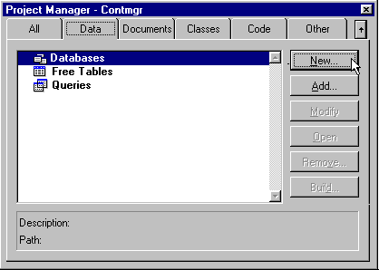
Figure 1. Data page of the Project Manager
To add a new database, open the Data page of the Project Manager (always begin development through the Project Manager). Upon clicking the New button, Visual FoxPro displays the Create dialog. As the database name, enter CONTMGR.
Upon returning to the Project Manager, you should now see a plus sign to the left of the word Databases. This symbol indicates that additional levels exist under the current level, database names in this case.
Using a naming convention to name each data item
While Visual FoxPro does not require a naming convention, using one makes reading code clearer.
Traditionally, FoxPro limited field names to ten characters. However, with Visual FoxPro 3.0 and 5.0, you can define field names with up to 128 characters, but only if the field is defined in a table bound to a database. A stand-alone table, called a free table, still has a ten-character limit.
Many field naming conventions have been devised to help make programs more readable. The current recommended standard prefixes each field with a single character defining its type.
Type Prefix Characters
| Type | Prefix | Example |
| Array | a | aMonths |
| Character | c | cLastName |
| Currency | y | yProdCost |
| Date | d | dBirthDate |
| DateTime | t | tRecordStp |
| Double | b | bAnnual |
| Float | f | fMiles |
| General | g | gSounds |
| Logical | l | ltaxable |
| Memo | m | mDescript |
| Numeric | n | nAge |
| Picture | p | pProdPict |
If the same field appears in multiple tables, you should make the characters after the prefix character exactly the same in each table. For example, suppose you store a style field in several tables. If style has the same meaning in each table, you might have:
| cStyle | for the style in the order file |
| cStyle | for the style in the product file |
| cStyle | for the style in the inventory file |
However, if style means something different in each table, the characters after the prefix should uniquely reflect this difference:
| cCustStyle | for customer style |
| cProdStyle | for product style |
| cClothStyle | for cloth style |
Because the same field name can appear in more than one table, always precede it with the file alias when used in code as shown below:
contact.cLastName
maildate.dMailDate
Use case to make variables readable
Notice in the above that the field names do not include spaces or underscores. This convention relies on the fact that the first capitalized letter indicates the beginning of the unique portion of the field name and the end of the prefix. Also, when the field name consists of two or more words, the first letter of each word begins with a capital letter. The rest of the characters are always lowercase.
Keep in mind that while you may enter variable names with upper and lower case as suggested above, Visual FoxPro is not case sensitive. It really doesn't care whether the variable is called dMailDate or dmaildate, both variables represent the same data memory location. This means that the burden of following a naming convention is solely on you.
Following a naming convention generates the following benefits:
Caution Despite the recommendation to use upper and lowercase, the Visual FoxPro Table Designer supports only lowercase. To make matters more confusing, commands like DISPLAY STRUCTURE list field names in uppercase. The Browse and Edit commands label column headings by displaying field names with initial caps only. Thus, there is no way to differentiate case in a table name. This is one reason why some developers use the underscore character after the prefix, or even between major words. For example, would the field C_RAP make more sense in a table listing types of music or would you prefer CRAP?
Designing tables
The most important thing that you can do when starting a new application is to carefully design the structure of your tables. A poorly structured database results in very inefficient code at best. At worst, it makes some features nearly impossible to implement. On the plus side, a well-designed set of tables helps you write programs faster. You can take advantage of queries and SQL SELECT statements to retrieve and maintain data. Finally, reports that may have required awkward manual coding under another structure almost write themselves with the report generator using normalized tables.
Functional dependencies
Assuming that you have already decided what data fields you need, the next step is to divide them into tables (of course, you could put all the fields into a single table). Even without normalization rules, it should be obvious that you do not want to repeat all the information about contacts, companies, and contact details for each phone call you make. One way to divide fields into separate tables is through functional dependency analysis.
Functional dependency defines the relation between an attribute (field) or a group of attributes in one table to another attribute or group of attributes in another. Therefore, you need to see which fields depend on other fields. For example, a person's last name depends on their Social Security number. For any given Social Security number (person), there is only one corresponding name—not necessarily a unique name, but still only one name (maybe).
On the other hand, a Social Security number does not depend on a name. Given a person's last name only, there may be dozens, if not hundreds, of Social Security numbers. Even if you add a first name to the last, it still might not uniquely identify a single social security number. Imagine how many Bob Smiths there are. Thus, you can conclude that a last name is functionally dependent on Social Security, but not the other way around.
After considering functional dependencies, you might have a table of contacts, another for contact details, one for company information, and one defining company types.
Data normalization
Functional dependency analysis helps define your tables, but the real test is data normalization. While there are five primary rules of data normalization and dozens of sub-rules, your tables should obey at least the first three rules, which we will cover here.
The first normal form eliminates repeating fields and non-atomic values. First, what is an atomic value and will it explode upon use? An atomic value means that the field represents a single thing, not a concatenation of values; just as, an atom represents a single element.
Another common problem addressed by the first normal form is repeated fields. Again, it was not unusual for early database developers to hard code the number of items a customer could order. They did this by placing multiple product IDs and related fields in the same record as the general order information. An example is shown in Figure 2 below.

Figure 2. Pre-normal order table
Suppose your order file allowed for four order items. It would be difficult to search the database to determine the sales of each product. Reports that display a list of customers who order specific products are similarly difficult to produce. In fact, most reports need complex hand coding, so they can search each field. As a result, reports tend to be error prone and require more time to execute.
Then you might need to increase the number of possible products the customer can buy. But how many is enough? Five? 10? 20? If you select 20, what if most customers only order two or three items? The resulting table wastes a lot of space. More importantly, depending on the way the code reads these fields, it may spend a lot of time processing empty fields. One alternative is to define a table with a variable number of fields. This is not an option in Visual FoxPro.
The solution is to use first normal form to replace repeating fields with a single field. It then adds as many records as necessary (one per ordered item).

Figure 3. First normal orders table
This first normal form is called structural or syntactic normalization.
Intuitively, you may not like the first normal solution. For one thing, it repeats several values, not within records, but across multiple records.
The second normal form requires that each column be dependent on every part of the primary key.
Because of the transformation performed by the first normal form, OrderId is no longer unique; neither is any other single field. However, the combination of OrderId and ProdId may be unique. Using this as a working assumption, examine the other fields to see if they depend on the new composite primary key.
Does ProdName depend on the key OrderId and ProdId? This is a trick question. In some ways it does but it does not depend solely on the full key. Rather, it depends solely on a portion of the key, the ProdId field. Therefore, this field fails the second normal form. Therefore, ProdName should be removed and placed in a separate table with ProdId as the primary key.
Similarly, OrderDate depends only on OrderId, not the combination of OrderId and ProdId. The same is true for OrderNet. Therefore, according to the second normal form, you need to remove these fields and place them in a separate table, along with a copy of the field they depend on, OrderId. This results in three tables. One with a primary key only on OrderId named ORDERS3. One with the primary key only on ProdId named PRODUCT3. And the last one, which contains a primary key on OrderId and ProdId named DETAIL3. These new tables are shown below:
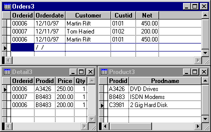
Figure 4. Second normal orders table
By merely following the rules of normalization, you have taken the original order data and derived a structure that consists of three tables. One table contains information about the overall order, another contains details on each order, and the last contains product information. This example makes an assumption that an item is ordered as a single quantity. This assumption is very restrictive. You may want to include a quantity field for each ordered item. The product ID can still only appear once per order; but now the quantity field can identify multiple purchases of an item within an order. This field can be a positive (purchases) or negative (returns) integer. The only value not allowed is 0. This field has been added to the DETAIL3 structure shown in the above figure.
To associate the information in ORDERS.DBF with ORDITEMS.DBF, you form a relation between them based on the common field OrderId. This is a one-to-many relation because for every order in ORDERS.DBF, there can be more than one record in ORDITEMS.DBF. Similarly, you can relate the DETAIL3 and PRODUCT3 tables through the common field ProdId. Now there is no limit to the number of items the customer can order, from zero items to millions. Programs, when written to use related files, handle all situations equally well.
Hint If the primary key of a table is a single field and if the table is already in first normal form, it is automatically in second normal form.
To reach the third normal form, the table must already be in first and second normal form. Next, verify which field or combination of fields represents the primary key for the table.
The third normal form requires that each non-key column dependent on the primary key and only the primary key.
To be in third normal form all non-primary fields must depend solely on the primary key. First decide whether Quantity depends solely on the key field combination OrderId and ProdId. The answer is yes, because it determines the number of items of a specific type within an order. It does not tell you the total quantity of items within an order or the number of any particular product sold.
On the other hand, suppose we add a field CustId to the orders table so we do not have to enter the entire customer name with each order. In this case, Customer really depends on CustId, not OrderId, which is the primary key in ORDER3. Therefore, it should be removed from ORDER3 and placed in a separate table with CustId as the primary key field.
The following tables show the final structure of this simple problem.
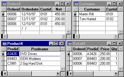
Figure 5. Third normal orders form
You may have reached this structural conclusion independently from your analysis of functional dependencies. Remember, normalization rules merely reinforce functional analysis.
While not formally a part of normalization, you usually want to avoid including fields that can be derived from other fields in the same or related tables. For example, you may not want to include an order total field in the order file. If the detail file contains the price of each item ordered, it is safer to sum the individual prices to determine the order total. Of course, the amount paid may go on the order table as a check against the total due. Think of it this way: the customer typically pays against an order, but is billed based on individual items.
Perhaps you feel overwhelmed with these rules. Actually, with practice, you will begin thinking of your data in terms of normalized files right from the start.
After defining your data requirements and defining the structure of your tables, you are ready to begin creating their structure. Visual FoxPro supports several ways to create tables.
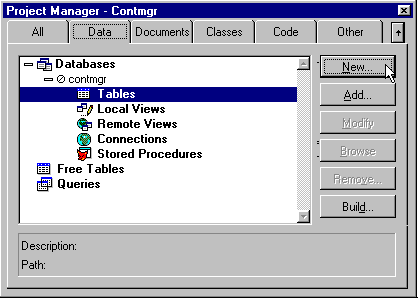
Figure 6. Add a table to a database
If you have an existing database in a project, simply open the database by clicking on the plus sign to the left of its name. This opens five levels or types of objects that a database can hold. These are:
Select Tables and click the New button. This opens a three-button dialog that allows you to choose how to open a new table. You can create the table using the Table Wizard. If you are familiar with manually defining table structures, simply click the New Table button.
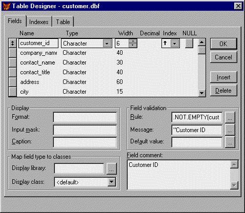
Figure 7. Define fields and their properties
If you create the table manually, note that you can define several field properties that were not available prior to Visual FoxPro. New field properties include:
Caption: This property can be used to display a text label before the field when you drag the field from the data environment onto a form. Captions are also used in place of field names when you browse or edit tables.
Field Validation Rule: Visual FoxPro executes this expression each time the field value changes. The most common use of the validation rule is to check if the new field value is acceptable. The validation rule must return a true (.T.) or false (.F.). If false is returned, focus stays in the field (the user cannot move off the field) until a value of true is returned. This is also known as declarative validation as opposed to procedural validation, which you must place as a procedure or function in each program that modifies the field.
Message Text: This text appears when the validation rule returns a false value and can be so much more informative than an Invalid Value message.
Default Value: This value is placed in the field when a new record is added to the table.
Format: Specifies input and output formatting for a control's value property. Mimics the behavior of the FUNCTION clause. Codes used here apply to the entire field.
Input Mask: Determines the format of the user's input on a character by character basis.
Field Comment: This free-form text area provides a long description for the field and appears after the Description label when you highlight the field name in the Project Manager. Use this field to document your fields.
Map Field: These options allow you to map specific classes each field in the table from your own custom class library. They are used when you drop and drag the fields from the data environment to a form. Note that you can specify both the class library and the class itself.
The most common type of index is a regular index or a normal index. You can use any field or fields in a table when creating a regular index. An index entry is created from every record in the table. Entries do not have to be unique. When they are not unique, a regular index includes a separate pointer to each record having the same value.
You use regular indexes extensively to define sort orders and to improve query performance. Figure 8 shows some index definitions for the CUSTOMER table.
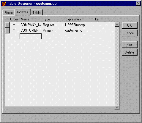
Figure 8. Defining indexes
In a CONTACT table, the contact's last name may not uniquely identify every record in the table. You may have customers Bill Jones and Kevin Jones. Therefore an index on the last name has repeated values, but you can use it as a regular index.
The second basic type of index is a unique index. Like a regular index, it can be created using any field or fields from a table. However, if more than one record has the same value for the index, only the first occurrence is added to the index.
For example, a unique index on cLastName in the CONTACT table may not include every record in the index, either Bill Jones or Kevin Jones would appear, but not both. If you added Bill Jones first, then the index would only point to Bill Jones. If you later delete Bill Jones, the index does not automatically add Kevin Jones.
Tip If you use an unique index, either recreate it each time you need to reference records, or at least use the REINDEX command to refresh it.
Two new index types introduced in Visual FoxPro require that the field values be unique in every record. These index types are called candidate indexes and primary indexes.
Every table should have a field or a combination of fields that unique identify each record. If a single field cannot be unique, the next best alternative is to use a combination of fields. For example, you might include cLastName and cFirstName to make a Candidate index. But what if you have contacts Jim T. Kirk and Jim C. Kirk? You may be tempted to add another field to the index for the contact's middle initial. But such an index does not guarantee uniqueness. Some programs attempt to combine portions of a contact's last name with the last four digits of their phone number plus their zip code (maybe even age, sex, title of their favorite Star Trek movie, and favorite web site address or newsgroup). In the end, it's easier to just assign a sequential contact ID to a new contact to uniquely identify each record. Because indexing this field generates a unique index that includes every record, it is a candidate index.
It is possible to have more than one candidate index for a table. However, one candidate index is generally assigned the duty of primary key. A primary key's main purpose is to form relations with other tables.
Never use just a letter to identify a work area such as A.cLastName. Such a practice restricts programs to always opening tables in the same work area. When you write generalized code that more than one procedure can call, you cannot always guarantee a work area's availability for a table. Therefore, always reference fields by their table alias.
When you use a variable without an alias identifier, Visual FoxPro makes the following assumptions about whether you mean to use the table variable or the memory variable:
Tip You can override these assumptions in the last two statements by prefixing variables with a table alias. If the variable is a memory variable, prefix with m.
For example, the following code line takes the table variable Quantity and adds sale quantity (SaleQty) to it. It then saves the sum in the memory variable Quantity.
Quantity = Quantity + SaleQty
If you run this statement in your code, you may wonder why quantity never seems to increase. The following redefined statement using the recommended naming convention makes the assignment clearer:
m.nQuantity = m.nQuantity + m.lnSaleQty
It tells us that nQuantity is a numeric variable saved to a memory variable from a table (because the prefix has only a single character). It also clearly adds a local numeric memory variable, lnSaleQty, representing the sales quantity.
Having now defined the tables and indexes you need for your application, you can define relations between the tables. You can still use the SET RELATION TO command used in prior versions of FoxPro, but as you know, you have to reset the relation in every program that uses the files.
Visual FoxPro provides a better alternative through the services of the database container. You can define Persistent Relations. A Persistent Relation is a relation enforced by the Visual FoxPro engine rather than from your code. For example, there is an obvious persistent relation between an ORDERS table and the DETAILS table. Visual FoxPro implements this feature through Referential Integrity.
In general, referential integrity defines which operations are permissible between tables connected with relations. The basic premise is that a primary key value in the parent table must have a corresponding lookup or foreign key in another table (called the child table). Referential integrity treats records that do not meet these criteria as invalid.
There are several ways to implement referential integrity. You need to decide what method best suits the data. As an example, consider the basic relation between general order information and detail order information.
The orders table typically contains information unique to the order as a whole. This information might include an order number, the order date, the customer's name, and many other fields. The order detail file contains specifics on the individual items ordered, such as the order number, product ID, quantity ordered, unit price, and so on. The relation that ties these two tables together is usually the order number.
When you add a record to the order table, you do so with the intent of adding details to the order detail table. After all, an order without details is not a complete order. Similarly, you would never think of adding details to an order details file without also adding an order record. In this example the order file is the parent and the order details file is the child table. The analogy is that you can have a parent without a child, but you cannot have a child without a parent.
Visual FoxPro adds a powerful new feature by providing engine-based referential integrity. To access the Referential Integrity (RI) builder:
The first method shows a menu containing Referential Integrity rules, while the second displays a command button in the dialog box. Selecting either method displays the builder shown below. The Referential Integrity Builder consists of a three-page page frame, one page each for updating, deleting, and inserting records.
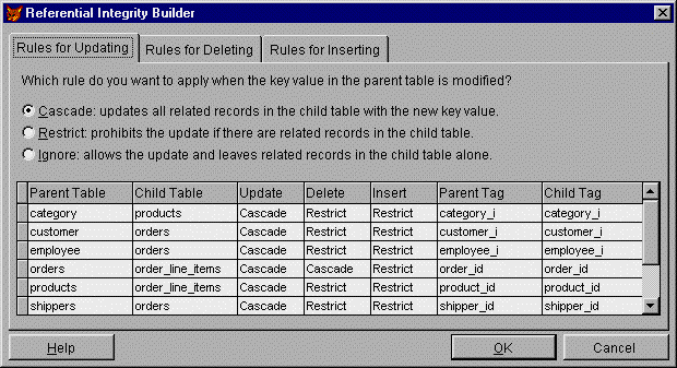
Figure 9. The Referential Integrity Builder
The bottom half of the builder lists each relation on a separate line or row. The columns across the row name the parent and child tables. Next follows three columns for the Update, Delete, and Insert Integrity rules. Initially, these all say Ignore. However, as shown, you can define rules for each relation and action. Finally, the last two columns define the parent and child tags involved in the relation.
Only the referential rule columns can be modified. If you select any of these columns by clicking them, a drop-down-arrow buttons appears that, when pressed, displays the referential options. These options are also defined in the page frame in the upper half of the builder.
Each referential action has its own page that lists the available options. For example, the referential options available when updating the key value in a parent table include:
As you can see, each of these options has an option (radio) button. Clicking the button changes the selected rule for the highlighted relation in the bottom half of the builder. Thus you have two ways to select the referential rules.
The rules defined for deleting parent records are similar to those for updating. However, the rules for inserting records apply from the child side of the relation. The two possible rules provided here are:
After you have defined the referential integrity rules for each relation and action, click OK to exit the builder. For example, you might want to cascade key updates made to the CUSTOMER table to the ORDER table. On the other hand, you might want to restrict deletion of CUSTOMER records if ORDER records still exist. Finally, you may want to restrict the entry of an ORDER record if the customer key does not exist.
When you click OK, the builder displays a dialog box asking you to save your changes, generate the RI code, and exit. This process creates a set of triggers and stored procedures in the database. If the database had previously defined triggers or a stored procedure, it makes a backup copy before overwriting it. Therefore you should define referential integrity between tables before defining any field validations or other stored procedures.
After the Referential Integrity Builder completes this task, you can open the Table Designer and select Table Properties to view the added triggers. Or you can view the stored procedures by clicking the Edit Stored Procedure button in the Database Designer toolbar.
Caution If you make changes to any of the tables involved in referential integrity, their indexes, or persistent relations, rerun the RI Builder. This revises the code as appropriate due to the changes made.
Just as field level validation checks an individual field whose value has been changed before accepting it, table validation can check any field or combination of fields before accepting a record change. This is especially useful when:
As with field validations, you can also specify validation text to be displayed should the record fail the test.
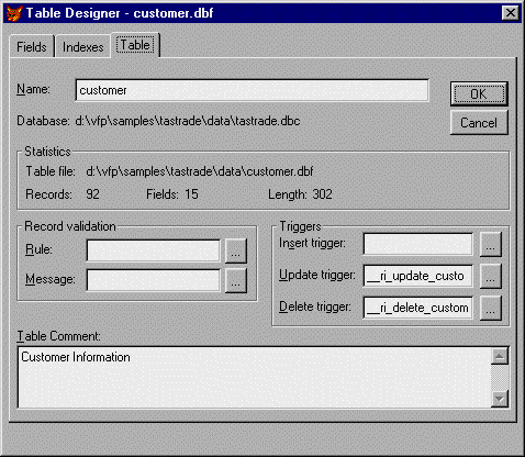
Figure 10. Defining table properties
An important point is that it is NOT possible to use a procedure or function in either the field or table validations that will "correct" the value. Changing the value of any field in the field validation itself would lead to a potential endless loop. Thus Visual FoxPro prohibits changes to the current table during the validation procedure/function.
A trigger is an event that Visual FoxPro calls when you add, delete, or modify a record. The Referential Integrity Builder uses triggers as the means to call code that enforces the selected integrity rules. However, you can also use these same triggers to replace and/or augment what happens with changes to a table.
Suppose you have a reorder point in each item of your inventory file. A reorder point is a number that identifies at what inventory level you need to reorder an item if its current in-stock value drops below the reorder point. You could write code in each application that changes the inventory amount to check for this occurrence. However, errors can be introduced at a number of points. Some possibilities are:
A better method is to write the code to check this once, and then call that code from the Update trigger of the inventory table.
If the table already has a referential trigger for Update, merely append a call to your function or procedure with an AND.
The Referential Integrity Builder automatically places the code it generates in the stored procedures section of the database container. What may not be obvious is that this is also the best place to store any procedure or function you create for validations or triggers. By using the stored procedures section, Visual FoxPro is guaranteed to be able to find the code when it needs it. If you place this code in a separate file, or in a procedure library, Visual FoxPro can only find it if it happens to be:
Of course, you can store other "shared" code in the stored procedures, but generally you should only use this feature for code required to support the database.
Always copy/move your tables, indexes, and database containers as a group. Getting any one out of sync is a disaster. This applies especially to backups and restores.
If you delete a CDX file, you will have difficulty in opening the DBF since index tag names and specifically the primary key tag name are stored in the DBC.
If you move the table to a new directory relative to the database container (or vice versa) you will be prompted to locate the other to redefine the forward and backward links.
Never update the table or index structure without the database being open (such as through the use of utilities).
Do not open the database container (as a DBF) and modify it directly unless you really know what you are doing! This is especially true of the Properties field.