By Jeffrey Richter
March 15, 1997
Jeffrey Richter wrote Advanced Windows, 3rd Edition (Microsoft Press, 1997) and Windows 95: A Developer’s Guide (M&T Books, 1995). Jeff is a consultant and teaches Win32-based programming seminars.
This paper is intended for Win32® developers and is designed to provide an overview of developing applications for Microsoft® Windows® CE. The Windows CE operating system was built from the ground up for a new class of embedded, mobile, or consumer devices. This article walks developers through the Windows CE SDK and Visual C++® for Windows CE. More information on Windows CE development is available from http://www.microsoft.com/windowsce/developer.
Windows® CE is a new lightweight 32-bit operating system for the Handheld PC (H/PC) released by Microsoft in November 1996. Although Windows CE is making its debut in these PC companions, it is not specific to these devices. In the not-too-distant future you can expect to see it used for the global positioning system in your automobile, in your television set, and in other household appliances. Currently, Windows CE runs on Hitachi SH3 and MIPS processors. (Although Microsoft has dropped MIPS support for Windows NT®, Windows CE will continue to support MIPS.) Microsoft has announced that it is working on versions for Intel x86, Motorola Power PC, and ARM processors. For more information on Windows CE and the Windows CE SDK and Visual C++ for Windows CE, see http://www.microsoft.com/windowsce.
Windows CE is based on the Win32 API, so you already know how to write code for it. Microsoft put a lot of effort into making Windows CE development tools look and feel the same as the Win32 tools you are already familiar with. Basically, Windows CE supports a subset of the Win32 API and all you need to do is include a different set of header files. The Windows CE header files lack declarations for the Win32 functions that are not supported by Windows CE. Thus, if you try to use an unsupported function in your Windows CE application, you will get a compiler error.
Windows NT was the first operating system to natively support Unicode (where characters are 16-bit values). Making an application international-aware is much simpler when you take advantage of Unicode. Because many developers were not aware of Unicode and in order to ease the porting of existing applications, Microsoft actually made Windows NT work with both 8-bit and Unicode characters. Windows 95, on the other hand, is derived from the original 16-bit Windows source code that expects 8-bit characters for everything. Because of this, Windows 95 does not offer good Unicode support (although 32-bit OLE on Windows 95 is Unicode only).
Windows CE is a new operating system kernel and Microsoft expects heavy international penetration. To this end, Microsoft made Windows CE Unicode only. Due to the memory constraints on devices that run Windows CE, Microsoft chose to leave out support for 8-bit characters entirely. This means that you really must understand Unicode because you are forced to use it when developing for the Windows CE platform.
To develop an application for Windows CE, you’ll first want to use a technique called desktop emulation. The software required for using this technique is available at no charge and can be found on the MSDN Library (MSDN Library, Tools and Technologies, Visual C++ for Windows CE) or can be downloaded from the Windows CE home page (http://www.microsoft.com/windowsce/developer).
Desktop emulation allows you to develop software using your existing Win32 compiler on any x86 machine running Windows NT (Windows 95 and other CPU platforms are not supported at this time). The emulation environment is really just a special set of DLLs that get linked with your normal Win32 application. When you run the application on your Windows NT machine, the application behaves as though it is running on the H/PC itself. This allows you to develop software for Windows CE without actually owning any H/PC hardware, and makes it easy to track down and fix the big bugs. You also save time by not having to download the application to the device before you can test it. All of the Windows CE enhancements, such as Command Bars and the database, are accessible in the emulation environment. In fact, the only thing you cannot do under emulation is access physical hardware such as the infrared serial port.
After your application is functioning perfectly in the emulation environment, you’re ready to build it and test it on the H/PC device. The binary image file you build for desktop emulation will not run on the Windows CE platform—you must rebuild your application for the host processor. Even if your desktop machine and the H/PC are both x86-based CPUs, you must rebuild your application.
To build your application for an H/PC, you’ll need to get Visual C++ for Windows CE, which is a complete development environment that allows you to develop applications on your desktop using a cross compiler. Once your application image is built, the environment will download the EXE or DLL to the device. This allows you to run the application on the device and also allows you to debug the application remotely. Visual C++ for Windows CE contains cross compilers for all supported Windows CE processors and a set of tools for building and debugging software on the device.
Visual C++ for Windows CE will be released this spring, coinciding with the next major release of Visual C++ (version 5.0). Installation will be in two parts: installing the Visual C++ 5.0 compiler, and then installing the add-on Visual C++ for Windows CE. Of course, the product will ship with help files as well as many sample applications.
Writing applications for Windows CE in the Integrated Development Environment (IDE) is very similar to writing software for Windows NT or Windows 95. The only thing you need to be aware of is a new combo box in the toolbar that allows you to choose your target platform.
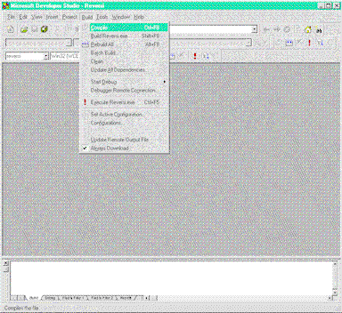
There are also three new items on the Build menu (see Figure 1). Two of these items let you control when the resulting binary image file is downloaded to the handheld device. The Update Remote Output File option downloads the binary image when you select it, while the Always Download option can be toggled on or off, telling the IDE whether or not to download the image after every successful build. If you turn the Always Download option on, you will never need to use the Update Remote Output File option.

Figure 1. The Build menu
The third new option, Debugger Remote Connection, allows you to select a protocol for remote debugging. When you select this option, the dialog shown in Figure 2 is displayed. You have two choices for remote debugging: Network (UDP) and Network (TCP/IP). Both allow you to remotely debug applications. The only difference is speed and reliability: UDP is much faster than TCP/IP debugging and should be used as the primary debugging method. Unfortunately, UDP is also a less reliable way of transferring data between the devices and sometimes does not work as expected. If you encounter problems with UDP, try switching to TCP/IP for debugging.
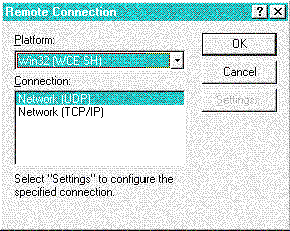
Figure 2. Choices for remote debugging
It could not be easier to set up your device for remote debugging. Just connect it to your PC the same way you would for replication (normal desktop-to-handheld communication). You use the H/PC’s serial cable to connect the serial port on the device to a serial port on your desktop computer. If you have a docking cradle for your H/PC, it will be connected to your desktop’s serial port and you will just place the device in the docking cradle. Once you have a physical connection between the device and your desktop, you will need to run some special software to create the network connection.
The H/PC contains a device driver that detects when a physical connection to the desktop machine is made and automatically starts the ReplLog.exe application (in the \Program Files\Communication\PC Link directory on the H/PC). On the desktop, you can run either the H/PC Explorer or the Remote Connection Server to manage the socket connection to the device. Once the network connection has been established, downloading the application and remote debugging are just menu clicks away.
This network connection allows you to establish a partnership between a device and your desktop, or for a device to connect as a guest to the desktop. Partnership allows you to exchange files, contacts, and schedule items between the device and the desktop machine. It also is the mechanism used by the development tools on the desktop. You can configure the software so that contacts and schedule items are always synchronized when the connection is initiated. This can take a few minutes, but it ensures that your device and desktop PC always share the most up-to-date data. Connecting as a guest, on the other hand, allows you to only exchange files between the device and desktop machine. This allows the connection to be initiated much more quickly since no synchronization occurs. You can download and remotely debug your applications regardless of the mode used for connecting the desktop PC and H/PC. The only information that needs to be transferred to the device is the application itself. All of the symbols and debugging information remain on the desktop machine.
Bear in mind that the H/PC is connected over a relatively slow serial connection and a network protocol is running over this connection to transfer the debugging information. As you might expect, this does not provide the same performance as debugging a native Win32 application or when debugging a Windows CE–based application in the emulation environment.
Using this mechanism for debugging works great for many Windows CE applications, but not all of them. Say, for example, you are writing an application that allows an H/PC to communicate with peripherals through the serial port. Since an H/PC only has a single serial port, it cannot be connected to a desktop PC while your application is running. To debug this type of application, you’ll need to either add a PCMCIA serial port or resort to other test methods, such as displaying debugging messages with MessageBox.
The remainder of this article discusses the myriad tools included with Visual C++ for Windows CE that will help you develop and debug applications.
The H/PC Explorer is an application that lets you view the file system of your Handheld PC and to synchronize its databases with the ones on your desktop PC. This tool works just like the normal Windows Explorer except that it allows you to also view files contained on the H/PC. With this tool you can copy, move, delete, and rename files and directories that are on your desktop or H/PC using the familiar Windows Explorer interface.
When you run HPC Explorer, it first tries to recognize the connected H/PC device. If the H/PC Explorer does not recognize the H/PC, you are asked if the H/PC is a guest or new partner. A guest is a machine that only shares files with the desktop, whereas a partner shares files and databases. If you were to bring your H/PC and connect it to a friend’s machine to download files, you would establish a guest connection since you do not want all of your friend’s contacts and appointments.
Once connected, if the device is a recognized partner and the software is properly configured for it, automatic synchronization will occur. Because each of these cases slows the initialization of the connection, if you are going to frequently break the connection to the H/PC, you may prefer to use the Remote Connection Server.
The Remote Connection Server is similar to the HPC Explorer since it creates a network connection between your desktop PC and the H/PC. It doesn’t, however, assume any relationship between the two, so no synchronization is attempted. This is ideal if you need to frequently disconnect the device for testing.
Consider the case of testing an application that transmits data through the infrared port on an H/PC. The hardware will not allow you to access the infrared port while the serial port is in use. Once the application is downloaded to the device, the connection to the desktop will need to be broken before the application can run successfully. If you are going to go through many iterations of compiling, downloading, and testing this application, you’re going to want to be able to connect the device to your desktop as quickly as possible. In this case, using the Remote Connection Server makes much more sense than using the HPC Explorer.
This application works much like the Win32 SDK Zoomin utility. But where Zoomin blows up a portion of your desktop’s screen, Remote Zoomin blows up a portion of the H/PC screen. When you run Remote Zoomin (on your desktop machine), you see a window like the one shown in Figure 3. You can capture the H/PC’s full screen contents by selecting the Get Full HPC Screen option from the Edit menu. You can select a smaller portion of the H/PC screen by selecting the Define HPC Zoom Area option and then using the stylus to draw a rectangle on the H/PC screen. The Refresh HPC Zoom Area option forces the window on your desktop machine to update itself so that it reflects the contents of the H/PC’s screen.
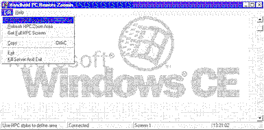
Figure 3. Remote Zoomin
The scrollbar on the right side of this window is used for increasing and decreasing the magnification of the image instead of panning the display. This makes it easy to capture and view images in detail. By the way, Figure 4 was captured using the Remote Zoomin tool.
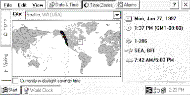
Figure 4. A sample image captured with Remote Zoomin
Like Windows 95 and Windows NT, Windows CE systems also use a registry. However, there is no RegEdit-like tool running on the H/PC itself that allows you to view and edit the registry. Instead, you can view and edit the H/PC’s registry using a desktop tool: Remote Registry Editor. This tool is very similar to its counterpart on the desktop. It allows you to view and modify registry keys and values on the device. The only difference that you will need to keep in mind is that all edits you make are not automatically sent back to the H/PC. In other words, after you change a registry key or value, you must select the File menu’s Export Registry to H/PC option so that your changes are flushed back to the H/PC.
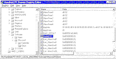
Figure 5. The Remote Registry Editor viewing the My Handheld PC\HKEY_LOCAL_MACHINE\Software\Microsoft\Clock registry key
The HomeDST data value is highlighted. The H/PC Clock application uses this data value to indicate if the user’s home city is currently in daylight savings time. The value of this key is either zero or 1 depending on the state of the check box in the Home Time Zone information in the Clock (see Figure 4). Take a look at this check box on the device and then look at the key in the Remote Registry Editor. Exit the Clock, change the value, and then select the Export Registry to H/PC option. Now, when you restart the Clock you’ll see the state of the check box has changed. If you now uncheck the box and exit the Clock, you will see that the state in the Remote Registry Editor is incorrect. To correct it, you select the Import Registry from the H/PC menu option to make the change display on the desktop.
The Remote Object Viewer (cleverly captioned Handheld PC Store Viewer by its programmer—see Figure 6) is a versatile application that allows you to view the object store on a remote H/PC device and on your local desktop machine.
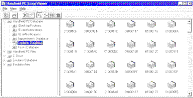
Figure 6. Handheld PC Store Viewer
Often, an application that you are developing will access files and databases (databases typically contain objects such as contacts, appointments, or tasks). However, if you are debugging your application using desktop emulation, these files and databases will not be on your local desktop machine. For you to debug your application using desktop emulation, the Windows CE emulation environment creates a file on your local desktop machine (\MSDEV\WCE\EMUL\PEGFILE.DAT). You use the Remote Object Viewer tool to copy any files or databases that your application requires from the H/PC device to this one file.
The Remote Object Viewer also gives you access to the Windows NT boot drive (drive C: in Figure 6). This allows you to copy files between your desktop machine and either the emulation environment’s file system or the H/PC file system. Figure 7 shows what each of the root nodes of the left-hand tree pane mean.
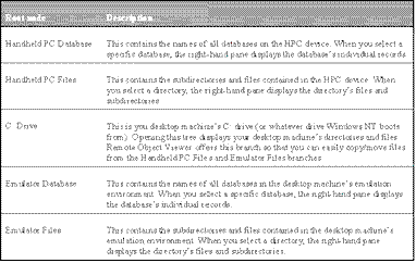
Figure 7. The Remote Object Viewer
The Remote Object Store also allows you to examine and edit records contained inside a database. In Figure 6, the Contracts Database is selected and the records inside the database are visible in the right-hand pane. If you double-click on a record, a property window is displayed that shows the record’s fields and values (see Figure 8).
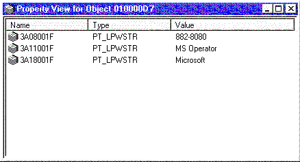
Figure 8. The Property View window
In the property window, you can change any of these properties by double-clicking on the property name and entering a new value.
The desktop Spy++ application is useful because it allows a developer to view the messages that are being sent to a particular window. Similarly, it is helpful to view the messages being sent to the windows of applications running on a Windows CE machine. So that it’s easier to work with, Remote Spy runs on the desktop computer rather than the H/PC itself. Once running (see Figure 9), you can select a window on the remote H/PC device and then see the messages sent to that remote window.
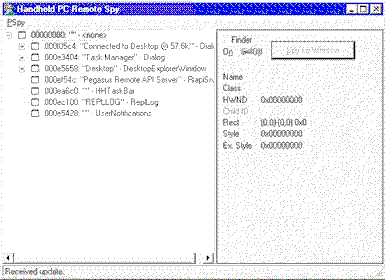
Figure 9. Handheld PC Remote Spy
When you start the Remote Spy application you are given a list of the windows on the H/PC. There is also the Finder that, when enabled, will highlight the outline of any window selected on the device and will display its handle and information in Remote Spy. Clicking on the Spy on Window button displays another window on the desktop. This new window displays the messages being sent or posted to the selected window on the H/PC.
As in the desktop version of this application, you can specify exactly which messages you want to see. As stated in the October 1996 MSJ article "What You Need to Know About ‘Pegasus,’ Microsoft’s Upcoming Handheld Device," Windows CE does not support non-client messages, so Remote Spy will never show these messages to you.
The last tool that comes with the Windows CE SDK is the Remote Memory Viewer. One look at this tool and it will be obvious that it was originally created to help the Windows CE kernel developers themselves. Then someone at Microsoft thought this tool would be useful information, but much of the information shown is internal to the kernel and might just be confusing. To fully understand this tool, what it shows you, and how to use it, you’ll need to have a good understanding of Windows CE’s memory architecture. First we’ll explain this architecture, then we’ll discuss the tool.
Let’s start by explaining the Windows CE kernel architecture and, specifically, how the system’s address space is partitioned. The most important thing to keep in mind is that a device running Windows CE typically has very little storage. There is no floppy or hard drive, so the only physical storage available is the ROM and RAM. There is usually about 4MB or 8MB of ROM, and either 2MB or 4MB of RAM. This severe limitation on storage has an enormous effect on the system’s architecture.
When the Windows CE operating system initializes, a single 4GB virtual address space is created. Unlike Windows 95 and Windows NT, all Win32 processes share this address space. This address space is divided up into 33 slots of 32MB (see Figure 10).
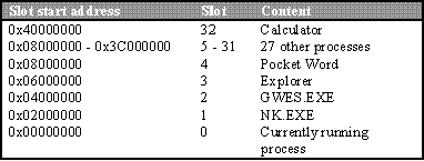
Figure 10. System address space
An attempt to read or write to any memory address above these 33 slots (address 0x42000000) always causes an access violation to be raised.
When a process initializes, Windows CE selects an open slot for the new process and populates the slot as shown in Figure 11.
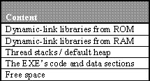
Figure 11. Memory slot population
This means that an application can use no more than 32MB of storage. But remember that the ROM and RAM typically only offer about 6MB to 12MB of storage in total, which needs to be shared by all running processes and the file system!
Within each slot, offset 0x00000000 to 0x0000FFFF is a 64KB region that is always free. This region is analogous to the same 64KB region on Windows NT that helps you catch NULL pointer assignments. Any attempt to read or write within this offset always causes an access violation to be raised. The EXE file’s code and data sections load starting at address 0x00010000 (64KB). Immediately following the EXE module are regions reserved for the primary thread’s stack and the process’s default heap. Any additional thread stacks and heaps will also be allocated around this area.
At the top of the 32MB slot, the system reserves a region that is large enough to contain all of the DLLs that are embedded in the system’s ROM. Even if an application you are writing only requires a few of the ROM DLLs, the system reserves a region large enough for all of them. This is a precaution that is taken in case your application calls LoadLibrary to load a ROM DLL at a later time. The ROM DLLs have all of the relocation information stripped out of them (to reduce their size), so they must load at their preferred base address or they will not be able to load at all! By reserving a region large enough for all the ROM DLLs, the system ensures that it will be able to load a ROM DLL any time you need it.
Like ROM DLLs, Windows CE requires that all RAM DLLs load at the same address in all process slots. For example, let’s say that process A is the first process to load the XYZ.DLL and that this DLL loads at offset 0x01800000 in process A’s slot. Now, if process B later calls LoadLibrary to also load XYZ.DLL, the system must be able to map XYZ.DLL to offset 0x01800000 in process B’s slot. If there is something else occupying this region in process B’s slot, its call to LoadLibrary fails, returning NULL.
Again, the reason why Windows CE works this way is to conserve memory. The first time XYZ.DLL is loaded, Windows CE performs all necessary fixups to the code so that references to any global and static variables inside the DLL are correct. If another process loads XYZ.DLL at a different memory address, the system must again perform fixups and this requires more memory. So instead of using the additional memory, the Windows CE architects chose to fail the call to LoadLibrary.
Windows CE always tries to load any RAM DLLs as high in your slot’s address space as possible to reduce the likelihood that the DLL will not be able to load because your address space is occupied by something else. This means you should try to keep the top portion of your process’s slot as empty as possible so you’re more likely to load the DLLs that you need. For example, you should avoid using the MEM_TOP_DOWN flag in calls to VirtualAlloc.
Slot 0, the bottommost 32MB, is special. What appears in this slot is the address space of the currently running process. For example, when a thread in Pocket Word is running (shown at slot 4 in Figure 10), Windows CE maps the 32MB region starting at 0x08000000 to slot 0’s region starting at 0x00000000. The process’s address space is actually visible to threads in the application via two different virtual memory addresses: slot 0 and the process’s original slot (slot 4 in this example). If you were to examine the thread’s registers, you’d see that the stack pointer and base pointer registers reflect addresses that are in slot 4 and the instruction pointer register reflects an address in slot 0. When you call functions that allocate memory like HeapAlloc, malloc, or VirtualAlloc, the addresses you get back are inside slot 0, not your process’s original slot.
Incidentally, you can determine which slot "owns" a memory address by looking at the top seven bits of the address. So, if you have an address of 0x15FF0000, the top seven bits are 0001010, which means slot 10. Of course, you can also take the address and shift it right by 25 bits.
Since all processes share a single address space, you would think that applications could easily corrupt each other just like they can in 16-bit Windows. However, Windows CE does not allow one application to corrupt another. Windows CE protects Win32 processes by altering page protections. When a thread in a process is active, all pages belonging to all other processes are protected. An executing thread can touch addresses in slot 0 and in its process’s original slot, but an attempt to touch an address in any other slot causes an access violation to occur.
On Windows CE, Win32 functions like CreateWindow, GetMessage, DrawText, and so on can be found in the COREDLL.DLL module. Every process running on Windows CE requires this module. The actual functions that create windows or draw text are implemented in another process, GWES.EXE (Graphics, Windowing, and Events Subsystem). When your application calls a function like CreateWindow, some form of interprocess communication must occur to get your request into the GWES.EXE process.
In most client/server architectures, this would be accomplished by using a shared memory block and by having the client thread transfer control to a server thread. In a limited-memory environment like Windows CE, this architecture would require the additional allocation of memory and the creation of additional threads (and their associated overhead). A more lightweight mechanism is needed here.
Let’s say that a Windows CE version of Calculator wants to create a window. To do this, Calculator’s thread pushes some arguments on its stack and then calls the CreateWindow function in COREDLL.DLL, which then causes a trap into kernel mode. The kernel now maps the GWES.EXE process into slot 0 and calls the actual function in GWES.EXE that creates a window. The thread that executes this code in GWES.EXE is Calculator’s—not GWES.EXE’s thread!
Also, note that when the kernel maps GWES.EXE into slot 0 it leaves Calculator’s slot unprotected. This allows the thread to successfully access Calculator’s address space—specifically, the arguments can be retrieved from Calculator’s thread’s stack. If any of the arguments passed to the function are addresses of data structures within slot 0, the kernel knows to automatically fix up the address so that it is in the client process’s slot instead of slot 0.
Performing "remote procedure calls" this way is really like mapping the server’s address space into the client’s address space, performing the desired action, and then removing the server’s address space again. The end result is a low-overhead, fast, and efficient RPC call.
Having discussed the Windows CE memory architecture, we can discuss the Remote Memory Viewer tool. The Remote Memory Viewer (see Figure 12) lets you view information about the processes, threads, and DLLs that are currently running on the H/PC.
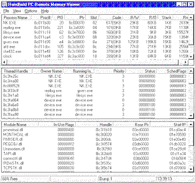
Figure 12. Remote Memory Viewer
The information displayed about each process includes the page counts (you can also set an option to display this information in KB) in addition to the process name, handle, and ID. Figure 13 details the information displayed in this section.
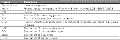
Figure 13. Details of memory views
There are several important things to note with respect to Windows CE version 1.01. Unlike Windows 95 and Windows NT, kernel object handles are not process-relative on Windows CE. Figure 12 shows that NK.EXE’s process kernel object handle is 0x8c011b00. If another process references handle 0x8c011b00, it would be affecting NK.EXE’s process. In Windows 95 and Windows NT, the HINSTANCE value that is passed to your application’s WinMain function identifies the memory address where the EXE module loaded into the process’s address space. On Windows CE, the HINSTANCE value is the handle of the process’s kernel object, not the load address. On Windows CE, the lower six bits of a process’s ID identify the slot where the process’s address space is located. The top 26 bits are used for uniqueness.
While the three statements made above are true for version 1 of Windows CE, they will not be true for future versions. Microsoft has been at work on version 2 of Windows CE, and much of this has already changed. Do not take advantage of this information in your application’s code, but feel free to take advantage of it while debugging your application.
Double-clicking on a process name brings up the Process Memory Map for the currently selected process (see Figure 14).
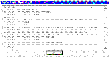
Figure 14. Process memory map
This memory map shows the pages currently allocated to the process and details each page’s type. Each line in the display begins with the address of a 64KB region (allocation-granularity boundary) of address space. After the address is a description of each page of storage in the region. Figure 15 shows the page designators and their descriptions.
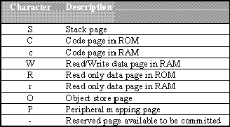
Figure 15. Page designators and descriptions
Any white space at the end of a line represents wasted free space that is necessary to get you to the next allocation-granularity boundary.
The second section of the main screen gives information about all of the currently executing threads in the H/PC. Each thread handle is displayed along with the process that owns (created) the thread, the process in which the thread is currently running, its current priority, its status, and scheduling flags. The distinction between the owning thread and running thread exists because of the way the system carries out RPC calls. For example, Figure 12 shows a thread with a thread handle of 0x8c3f33c8. The REPLLOG.EXE process created this thread. However, the thread has placed a call to a Win32 function, like GetMessage. Placing a call to GetMessage causes REPLLOG.EXE’s thread to run in GWES.EXE.
When you select a thread in the list view, its current priority is displayed in the radio buttons to the left of the window. You can change a thread’s priority by selecting the appropriate priority under the View/Set Thread Priority menu option. Figure 16 details the valid values and the priorities they represent.

Figure 16. Thread values and priorities
Note that on Windows CE, all processes belong to the normal priority class—the idle, high, and real-time priority classes are not supported. The Status value will have bit 9 set (0x0100) if the thread handle has been closed by its creator by calling CloseHandle after the call to CreateThread or CreateProcess, and it will be zero otherwise. Figure 17 details the values of the scheduling flags.

Figure 17. Values of scheduling flags
Finally, the third section of the Remote Memory Viewer display is devoted to DLL modules. Each entry shows the DLL’s name as well as some flags, the module’s handle, and the DLL’s base pointer (starting point in memory) and entry point (address of DllMain). In version 1 of Windows CE, the in-use flags indicate which processes are using the DLL. Each 1 bit indicates which process slots see the DLL. For example, Figure 12 shows that COMMCTRL.DLL’s in-use flags have a value of 0x00000648. This means that COMMCTRL.DLL is visible in four different process slots: 3, 6, 9, and 10.
For another example, you see that UNIMODEM.DLL’s in-use flags are set to 0x00000008. This means that only one process is using this DLL (since only a single bit is set) and that process resides in slot 3 (since bit 3 is set). If we look at the lower six bits of each process’s ID we discover that DEVICE.EXE is in slot 3. We can therefore conclude that DEVICE.EXE is the only process using UNIMODEM.DLL.
In Windows 95 and Windows NT, DLL modules never have associated kernel objects for them. However, in Windows CE, a DLL’s module handle identifies a data structure (not kernel object) that the kernel uses to keep track of loaded DLLs. Again, unlike Windows 95 and Windows NT, this value does not indicate the memory address of where the DLL loaded (its HMODULE).
The View/Kernel Summary menu option brings up a dialog box containing summary information for the resources currently used by the Windows CE kernel (see Figure 18).
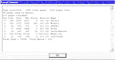
Figure 18. Summary of kernel resources
The top line of the display shows the page size in bytes, the total number of pages on the system, and the number of free pages. The next two lines show the number of pages used and the number of pages used by the kernel (the number of pages used by the kernel is included in the total number of used pages). After this comes several lines displaying various kernel objects. Figure 19 details the information displayed for each object.
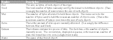
Figure 19. Information on kernel objects
The big advantage of Windows CE over other handheld computer operating systems is that it supports the Win32 API. This means that developers with experience building Windows-based software will be able to develop for the H/PC platform without having to learn a lot of new stuff. It also means that Microsoft can use many of their existing tools to help bootstrap development. As pointed out, Microsoft has been hard at work on version 2 of Windows CE and we can only assume that the development tools for Windows CE will greatly improve over time. For today, developers certainly have a set of useful and usable tools.
The information contained in this document represents the current view of Microsoft Corporation on the issues discussed as of the date of publication. Because Microsoft must respond to changing market conditions, it should not be interpreted to be a commitment on the part of Microsoft, and Microsoft cannot guarantee the accuracy of any information presented after the date publication. This document is for informational purposes only.
MICROSOFT MAKES NO WARRANTIES, EXPRESS OR IMPLIED, IN THIS SUMMARY.