Jason Black and Jon Christiansen
September 1997
The graphics display architecture in the Microsoft® Windows® CE operating system has been radically transformed in version 2.0. In version 1.0, the Graphics Device Interface (GDI) interfaced directly with the display hardware. In version 2.0, the GDI interfaces with one or more display drivers, which in turn interface with the display hardware. This display architecture gives Windows CE the capability of using a wide variety of display devices without the need to have a hard-coded interface routine for each device. The new Windows CE GDI thus combines versatility with a small footprint.
First, we will consider the elements that make a good Windows CE display driver. We'll discuss the device driver interface functions that display drivers should implement, as well as the graphics primitive engine classes that can be used to simplify the task of writing display drivers. GDI support for device drivers is also discussed.
Then, we will list detailed display buffer formats for each of the pixel depths supported by Windows CE, and discuss display hardware. Since the display drivers are the conduits between GDI and the display devices, the hardware needed to support the display drivers is, in effect, the hardware needed to support GDI.
Like much of Windows CE, the Display Driver Interface (DDI) is a subset of the Microsoft Windows NT® DDI. If you are not familiar with the Windows NT DDI, you may wish to read the display driver sections of the Windows NT Device Driver Kit (DDK) before writing your Windows CE display driver.
Windows CE uses only the basic graphics engine functions and driver functions from the Windows NT DDI. These differences between Windows CE and Windows NT have the following ramifications for Windows CE display drivers:
All Windows CE display drivers must implement a set of DDI functions that will be called by the GDI to initialize the display driver and draw to the display. In addition to the DDI functions, there is a set of Microsoft Visual C++® classes called the Graphics Primitive Engine (GPE) classes that display drivers can use to facilitate hardware acceleration. The sample display driver's implementation of the GPE Classes and their methods perform acceleration for S3Trio64-based display hardware. If your display hardware uses a different video chip set, you can change the implementation of the GPE methods to suit your hardware's capabilities.
Note that using the GPE classes is optional. You could write your display driver without them, at the expense of making your implementations of the DDI functions more complex. Note that the GPE classes as provided by Microsoft require that your display hardware have a flat frame buffer. If your display hardware does not (for example, if it uses a fixed-size moveable window to access the whole of display memory), it may not be possible to use the GPE classes. For more information, see the "Windows CE Display Hardware Recommendations" section of this article, especially the "Dirty Rect Drivers" subsection.
Windows CE display drivers differ from normal device drivers in a number of ways. The major difference is that they do not expose the stream input/output (I/O) interface, therefore, they are not managed by the device manager, so RegisterDevice is never called for them. As a result, there are no special device files or other file system entries that correspond to active display drivers. Display drivers are loaded when an application that needs to use the display driver calls CreateDC with the name of the display driver's .dll file. This causes Windows CE to load the display driver, and initialize it so that a device context can be returned to the calling application. The default display driver, of course, is loaded automatically.
The following table lists the DDI functions for both display and printer drivers. Display drivers should implement all of the display DDI functions listed here; printer drivers should implement all of the listed print DDI functions. However, only DrvEnableDriver must be exported from the display driver DLL. Therefore, only DrvEnableDriver must bear that name; the other functions can be called whatever you want because they are exposed to GDI through function pointers returned by DrvEnableDriver. No matter what they are called, follow the prototypes defined in the WinDDI.H file.
Table1. DDI functions
| Function | Purpose |
| DrvAnyBlt | Bit block transfer, with stretching or transparency |
| DrvBitBlt | General bit block transfer, with clipping and masking |
| DrvContrastControl | Allows software adjustment of the display hardware's contrast |
| DrvCopyBits | Sends GDI-created print band to printer driver |
| DrvCreateDeviceBitmap | Creates and manages bitmaps |
| DrvDeleteDeviceBitmap | Deletes a device bitmap |
| DrvDisableDriver | Notifies the driver that GDI no longer needs it and is ready to unload it |
| DrvDisablePDEV | Notifies the driver that GDI no longer needs a particular print or display device |
| DrvDisableSurface | Notifies the driver that GDI no longer needs a particular drawing surface |
| DrvEnableDriver | The initial entry point exposed by the driver that returns pointers to the other DDI functions to GDI |
| DrvEnablePDEV | Returns a PDEV, a logical representation of a physical display device, to GDI |
| DrvEnableSurface | Creates a drawing surface and associates it with a PDEV |
| DrvEndDoc | Sends any control information needed to finish printing a document |
| DrvFillPath | Fills a path with a brush |
| DrvGetMasks | Gets the color masks for the display device's current mode |
| DrvGetModes | Lists the display modes supported by the display device |
| DrvMovePointer | Moves the pointer with a guarantee of noninterference by GDI |
| DrvPaint | Paints a specified region with a brush |
| DrvPowerHandler | Called to handle power-up and power-down notifications |
| DrvQueryFont | Gets font metric information |
| DrvRealizeBrush | Creates a brush with parameters specified by GDI |
| DrvRealizeColor | Maps an RGB color onto the closest available color supported by the device |
| DrvSetPalette | Sets the display device's palette |
| DrvSetPointerShape | Sets the pointer to a new shape and updates the display |
| DrvStartDoc | Sends any control information needed to start printing a document |
| DrvStartPage | Sends any control information needed to start printing a new page |
| DrvStrokePath | Strokes a path |
| DrvTransparentBlt | Bit block transfer, with transparency |
| DrvUnrealizeColor | Maps a color in the display device's format onto an RGB value |
The sample display driver uses the GPE classes. While the GPE classes are optional, using them greatly facilitates the process of writing display drivers. If you use the GPE classes, you only need to provide the new code necessary to make your display hardware function correctly and to perform acceleration.
The GPE classes require that your display hardware uses a flat frame buffer. That is, the display's memory must lie in a contiguous memory range. Modifying the GPE classes to use a discontinuous frame buffer would require significant effort.
To create a display driver based on the GPE classes, use the following approach:
The Windows CE GDI provides some services to support display drivers, in the form of predefined structures with functions that act on them, and a few standalone C functions. Predefined structures provide support for brushes, clipping regions, palettes, stroke and fill paths, and translations. Standalone C functions provide support for device bitmaps and surfaces.
Table 2. GDI structures and functions
| Structure or Function | Purpose |
| BRUSHOBJ | Structure that represents a brush used for solid or patterned stroke and fill operations |
| BRUSHOBJ_pvAllocRbrush | Function that allocates memory for a brush |
| BRUSHOBJ_pvGetRbrush | Function that retrieves a pointer to the specified brush |
| CLIPOBJ | Structure that represents a clipping region |
| CLIPOBJ_bEnum | Function that enumerates clipping rectangles from a clipping region |
| CLIPOBJ_cEnumStart | Function that sets parameters for enumerating the rectangles in a clipping region |
| EngCreateDeviceBitmap | Function that causes GDI to create a handle for a device bitmap |
| EngCreateDeviceSurface | Function that causes GDI to create a device surface that the display driver will manage |
| EngDeleteSurface | Function that informs GDI that a device surface is no longer needed by the display driver |
| PALOBJ_cGetColors | Function that copies colors into a palette |
| PATHDATA | Structure that stores portions of a drawing path |
| PATHOBJ_bEnum | Function that enumerates PATHDATA records from a drawing path |
| PATHOBJ_vEnumStart | Function that readies a drawing path to have its component line segments enumerated |
| PATHOBJ_vGetBounds | Function that returns the bounding rectangle for a drawing path |
| XLATEOBJ | Structure used in translating colors from one palette to another |
| XLATEOBJ_cGetPalette | Function that retrieves colors from an indexed palette |
The Windows CE GDI supports displays with a wide variety of color depths and color models, from one-bit color to palletized color to true 32-bit RGB. Each format also supports several pixel-orderings, depending on whether access to the display memory is by bytes, two-byte words, or 4-byte DWORDs.
All display buffer formats assume that the order of pixels on the display is from left to right, and top to bottom. That is, pixel (0,0) is at the upper-left corner of the display, and pixel (width-1, height-1) is at the lower-right corner.
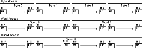
One-bit-per-pixel format is for simple black-and-white displays. Zero represents black, one represents white. Pixels are packed into bytes such that pixel (0,0) is packed into the highest-order bit of the first byte of display memory. Memory for this format can be arranged like this:

Two-bits-per-pixel format is typically used for four-level grayscale displays, although any 4-entry palette will work. Gray levels are represented according to the following table:
| Bit 1 | Bit 0 | Gray Level |
| 0 | 0 | Black |
| 0 | 1 | Dark Gray |
| 1 | 0 | Light Gray |
| 1 | 1 | White |
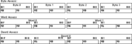
Memory for this format can be arranged like this:

Four-bits-per-pixel format is generally a palletized format. The frame buffer itself can be implemented either as two pixels packed into each byte, or as one pixel-per-byte. Memory for this format can be arranged like this:

If you choose to implement just one pixel per byte, the driver should represent the display mode as eight bits per pixel with a 16-color palette. The relevant bits in each byte should be the low-order nibble, while the high-order nibble should always be zero.
Eight-bits-per-pixel format should ideally use a software-changeable palette that maps eight-bit values onto 24-bit colors. Microsoft recommends using a palette that contains the default Windows CE palette for reasons of performance, compatibility, and image quality. Memory for this format can be arranged like this:

Fifteen- or sixteen-bits-per-pixel format is a masked format, and is not palletized. For either fifteen or sixteen bits per pixel, pixels are stored one per two-byte word; fifteen-bits-per-pixel format wastes the high-order bit of each word. Microsoft recommends using the following masks to extract red, green, and blue values:
| Color | Fifteen-Bit (5-5-5 RGB) | Sixteen-Bit (5-6-5 RGB) |
| Red | 0x7C00 | 0xF800 |
| Green | 0x3E00 | 0x07E0 |
| Blue | 0x001F | 0x001F |
As those masks show for fifteen bits per pixel, the low-order fifteen bits of each word contain the pixel's data. The unused bit should contain zero. Memory for this format can be arranged like this:

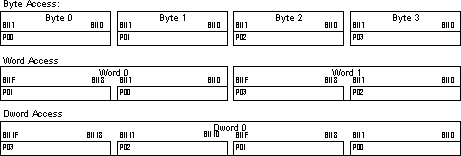
Twenty-four-bits-per-pixel format is a true-color format, in which each pixel stores eight bits for red, green, and blue. There are advantages and drawbacks to this format. The advantages are that image quality is very good, and because each pixel occupies exactly 3 bytes, they can be packed together without wasting memory. The drawback is that since half the pixels in this scheme cross DWORD boundaries, there is a performance penalty in accessing and decoding pixels. Memory for this format can be arranged like this:

Thirty-two-bits-per-pixel format is another true color format. This format does not cause pixels to cross DWORD boundaries, but is less efficient in memory use. There are two ways to arrange the color channels in this format. One puts blue in the least significant byte of each pixel, and the other puts red in the least significant byte. These options correspond to the PAL_BGR and PAL_RGB modes. You can use the following masks to extract red, green, blue, and alpha channels from each pixel:
| Color | PAL_RGB Mask | PAL_BGR Mask |
| Red | 0x000000FF | 0x00FF0000 |
| Green | 0x0000FF00 | 0x0000FF00 |
| Blue | 0x00FF0000 | 0x000000FF |
Memory for this format can be arranged like this:

Microsoft has several recommendations for display hardware used with the Windows CE operating system. These recommendations are both to improve performance and to facilitate your display driver development effort. You can still write a fully functional display driver, even if your hardware does not conform to these recommendations, or if it is too late in the design cycle for your product to alter the hardware design, at the expense of additional effort in implementing the driver and/or decreased performance.
Microsoft strongly recommends that your display hardware use a linear frame buffer; you should be able to both read and write to the buffer. All of your display's memory should be contiguous, and preferably, there should be one linear access window that covers the entire frame buffer. Hardware that does not meet this recommendation will require that you make substantial modifications to the GPE classes if you choose to use them. See the "Using GPE Classes" section of this article for more information.
Your display hardware should also use a supported combination of pixel format, packing, and pixel ordering. For more information, read the "Display Buffer Formats" section of this article. The display hardware's frame buffer should have the following properties:
If you wish to use the GPE classes to implement a display driver but your display hardware is not designed to support GPE classes (for instance, if the frame buffer is not linear) then you may want to consider writing a "dirty rect driver".
In this model, the GPE classes maintain an in-memory device-independent bitmap (DIB) that represents the frame buffer. GPE notifies the dirty rect driver whenever the in-memory DIB is modified. The dirty rect driver is responsible for copying the altered or "dirty" portion of the DIB to the display device, performing whatever conversions are necessary.
Dirty rect drivers come with significant costs in memory usage and execution speed. They should only be used as a last resort to support hardware that absolutely cannot be made compatible with GPE requirements.
Microsoft recommends that you use display hardware that can accelerate the following operations, in order of decreasing importance:
In version 2.0 of Windows CE, the display drivers play a critical role in the visual display architecture. Display drivers and display hardware that are created in accordance with the design strategies outlined in this paper will allow Windows CE–based devices to take full advantage of the enhanced graphical display capabilities of the new GDI.
For the Microsoft Windows CE Embedded Toolkit for Visual C++ 5.0, see the Microsoft Windows CE Web site (http://www.microsoft.com/windowsce/developer/prodinfo/vcceembed.htm). The toolkit will also be available to Universal Subscribers of the MSDN Library.
Also, be sure to take a look at the following articles, all available in the MSDN Library:
"Embedded Development with Microsoft Windows CE 2.0," by Franklin Fite Jr. and Randy Kath.
"Introducing the Windows CE Embedded Toolkit for Visual C++ 5.0," by David Pellerin.
"Microsoft Windows CE Graphics Features," by Jon Christiansen.
"Microsoft Windows CE Memory Use," by John Murray.
"The Microsoft Windows CE Communications Model," by Guy Smith.
"Real-Time Systems with Microsoft Windows CE," by John Murray.
"The Win32 Programming Model: A Primer for Embedded Software Developers," by David Pellerin.
The information contained in this document represents the current view of Microsoft Corporation on the issues discussed as of the date of publication. Because Microsoft must respond to changing market conditions, it should not be interpreted to be a commitment on the part of Microsoft, and Microsoft cannot guarantee the accuracy of any information presented after the date of publication. This document is for informational purposes only.
This White Paper is for informational purposes only. MICROSOFT MAKES NO WARRANTIES, EXPRESS OR IMPLIED, IN THIS DOCUMENT.