Grady Booch, Chief Scientist, Rational Software Corporation
egb@rational.com
A successful software organization is one that consistently deploys quality software that meets the needs of its users. An organization that can develop such software in a timely and predictable fashion with an efficient and effective use of resources, both human and material, is one that has a sustainable business.
There's an important implication in this message: the primary product of a development team is not beautiful documents, world-class meetings, great slogans, or Pulitzer-prize winning lines of source code. Rather, it is good software that satisfies the evolving goals of its users and the business. Everything else is secondary.
Unfortunately, many software organizations confuse "secondary" with "irrelevant." To deploy software that satisfies its intended purpose, you have to meet and engage users in a disciplined fashion, so as to expose the real requirements of your system. To develop software of lasting quality, you have to craft a solid architectural foundation that's resilient to change. To develop software rapidly, efficiently, and effectively with a minimum of software scrap and rework, you have to have the right people, the right tools, and the right focus. To do all this consistently and predictably, with an appreciation for the lifetime costs of the system, you must have a sound development process that can adapt to the changing needs of your business and technology.
Modeling is a central part of all of the activities that lead up to the deployment of good software. We build models to communicate the desired structure and behavior of our system. We build models to visualize and control its architecture. We build models to better understand the system we are building, often exposing opportunities for simplification and reuse. We build models to manage risk.
If you want to build a doghouse, you can pretty much start with a pile of lumber, some nails, and a few basic tools such as a hammer, a saw, and a tape measure. In a few hours, with little prior planning, you'll likely end up with a doghouse that's reasonably functional, and you can probably do it with no one else's help. As long as it's big enough and doesn't leak too much, your dog will be happy. If it doesn't work out, you can always start over, or get a less demanding dog.
If you want to build a house for your family, you can start with a pile of lumber, some nails, and a few basic tools, but it's going to take you a lot longer, and your family will certainly be a lot more demanding than the dog. In this case, unless you've already done it a few dozen times before, you'll be better served by doing some detailed planning before you pound the first nail or lay the foundation. At the very least, you'll want to sketch out several ideas of what you want the house to look like. If you want to build a quality house that meets the needs of your family and of local building codes, then you'll need to draw some blueprints as well, so that you can think through the intended use of the rooms and the practical details of lighting, heating, and plumbing. Given these plans, then you can start to make reasonable estimates of the amount of time and materials this job will require. Although it is humanly possible to build a house alone, you'll find it to be much more efficient to work with others, possibly subcontracting out many key parts or buying prebuilt materials. As long as you stay true to your plans and stay within the limitations of time and money, then your family will likely be satisfied. If it doesn't work out, you can't exactly get a new family, and so it's best to set expectations early and manage change carefully.
If you want to build a high-rise office building, it would be infinitely stupid for you to start with a pile of lumber, some nails, and a few basic tools. Since you are probably using other people's money, they will demand to have input into the size, shape, and style of the building. Often, they will change their minds, even after you've started building. You will want do to an extensive amount of planning, because the cost of failure is high. You will be just a part of a much larger group responsible for developing and deploying the building, and so the team will need all sorts of blueprints and models to communicate with one another. As long as you get the right people and the right tools and actively manage the process of transforming an architectural concept into reality, you will likely end up with a building that will satisfy its tenants. If you want to keep building buildings, then you will want to be certain to balance the desires of your tenants with the realities of building technology, and you will want to treat the rest of your team professionally, never placing them at any risk or driving them so hard that they burn out.
It's a curious thing, but a lot of software development organizations start out wanting to build high rises, but approach the problem as if they were knocking out a dog house.
Sometimes, you get lucky. If you have the right people at just the right moment in time and if all the planets align properly, then you might, just might, get your team to push out a software product that dazzles its users. Typically, however, you can't get all the right people (the right ones are often already over committed), it's never the right moment (yesterday would have been better), and the planets never seem to align (instead, they keep moving, entirely out of your control). Given the increasing demand to develop software in Internet time, development teams often fall back on the only thing they really know how to do well—namely, pound out lines of code. Heroic programming efforts are legend in this industry, and thus often it seems that working harder is the proper reaction to any crisis in development. Oft times, however, these are not necessarily the right lines of code, and furthermore, some projects are of such a magnitude that even adding more hours to the work day is just not enough to get the job done.
If you really want to build the software equivalent of a house or of a high rise, the problem is always more than just a matter of writing lots of software—in fact, the trick is in creating the right software and in figuring out how to write less software. This makes quality software development an issue of architecture and process and tools. Even so, many projects start out looking like doghouses, but then grow to the magnitude of a high rise, simply because they are a victim of their own success. There comes a time when, if there was no consideration given to architecture, process, or tools, that the doghouse now grown into a high rise collapses from its own sheer weight. The collapse of a doghouse may annoy your dog; the failure of a high-rise will have a material impact on its tenants.
Unsuccessful software projects all fail in their own unique ways, but all successful projects are alike in many ways. There are certainly many elements that contribute to a successful software organization, but one common thread is the use of modeling.
Modeling is a proven and well-accepted engineering technique. We build architectural models of houses and high rises to help users visualize the final product. We may even build mathematical models in order to analyze the effects of winds or earthquakes on our buildings.
Modeling is not just a part of the building industry. It would be inconceivable to deploy a new aircraft or an automobile without first building some models, from computer models to physical wind tunnel models, to full-scale prototypes. New electrical devices, from microprocessors to telephone switching systems require some degree of modeling in order to better understand the system being built and to communicate those ideas to others. In the motion-picture industry, storyboarding is central to any production, and each storyboard represents a model of the project being produced. In the fields of sociology, economics, and business management, we build models so that we can validate our theories or try out new ones with minimal risk and cost.
What, then, is a model? Simply put: A model is a simplification of reality.
A model provides the blueprints of a system. Models may encompass detailed plans, as well as more general plans that give a 30,000-foot view of the system under consideration. A model may be structural, emphasizing the organization of the system, or it may be behavioral, emphasizing the dynamics of the system.
Why do we model? There is one fundamental reason: We build models so that we can better understand the system we are creating.
Through modeling, we achieve four things:
Unified Modeling Language (UML) is a graphical language for visualizing, specifying, constructing, and documenting the artifacts of a software-intensive system. UML gives you a standard way to write a system's blueprints, covering conceptual things such as business processes and system functions, as well as concrete things such as classes written in a specific programming language, data base schemas, and reusable software components. UML is a widely adopted standard that represents best practices and lessons learned from well over a decade of experience of modeling complex software-intensive systems.
Further information about UML is provided in the appendix at the end of this paper.
Visualizing, specifying, constructing, and documenting a software-intensive system demands that the system be viewed from a number of different perspectives. Different stakeholders—end users, analysts, developers, system integrators, testers, technical writers, and project managers—each bring a different agenda to a project, and each look at that system in different ways at different times over the life of the project. A system's architecture is perhaps the most important artifact that can be used to manage these different view points and so control the iterative and incremental development of a system throughout its life cycle.
What exactly is software architecture?
Software architecture encompasses the set of significant decisions about the organization of a software system: the selection of the structural elements and their interfaces by which a system is composed, together with their behavior as specified in the collaborations among those elements, the composition of these structural and behavioral elements into progressively larger subsystems, and the architectural style that guides this organization.
Software architecture is not only concerned with structure and behavior, but also with usage, functionality, performance, resilience, reuse, comprehensibility, economic and technology constraints, and aesthetic concerns.
Architecture is design, but not all design is architecture. Rather, architecture focuses upon significant decisions, where significant is measured by the impact of changing that decision. For this reason, architectural decisions tend to concentrate upon identifying and controlling the seams in a system, which are described in terms of interfaces and mechanisms and so typically mark the units of change in the system.
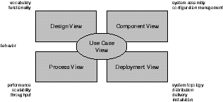
As the following figure illustrates, the architecture of a software-intensive system can best be modeled by five interlocking views, with each view being a projection into the structure and behavior of the system, and each view focused on a particular aspect of that system.

Figure 1. The views of a software architecture
The design view of a system encompasses the classes, interfaces, and collaborations that form the vocabulary of the problem and its solution. This view primarily supports the functional requirements of the system, meaning the services that the system should provide to its end users. With UML, the static aspects of this view are captured in class diagrams and object diagrams and the dynamic aspects of this view are captured in interaction diagrams, statechart diagrams, and activity diagrams.
The process view of a system encompasses the threads and processes that form the system's concurrency and synchronization mechanisms. This view primarily addresses the performance, scalability, and throughput of the system. With UML, the static and dynamic aspects of this view are captured in the same kinds of diagrams as the logical view, but with a focus on the active classes that represent these threads and processes.
The deployment view of a system encompasses the nodes that form the system's hardware topology, upon which the system executes. This view primarily addresses the distribution, delivery, and installation of the parts that make up the physical system. With UML, the static aspects of this view are captured in deployment diagrams, and the dynamic aspects of this view are captured in interaction diagrams, statechart diagrams, and activity diagrams.
The component view of a system encompasses the components that are used to assemble and release the physical system. This view primarily addresses the configuration management of the system's releases, made up of somewhat independent components that can be assembled in various ways to produce a running system. With UML, the static aspects of this view are captured in component diagrams, and the dynamic aspects of this view are captured in interaction diagrams, statechart diagrams, and activity diagrams.
As this figure goes on to show, requirements are the main drivers of any software architecture. By drivers, we mean the most important forces that shape the architecture. Requirements manifest themselves primarily in the use-case view. The use-case view of a system encompasses the use cases that describe the behavior of the system as seen by its end users, analysts, and testers. With UML, the static aspects of this view are captured in use-case diagrams, and the dynamic aspects of this view are captured in interaction diagrams, statechart diagrams, and activity diagrams. Additionally, there's often a need for supplemental requirements, which encompass all of the nonfunctional requirements of the system as seen by its end users, analysts, and testers. These elements typically have no meaningful visual model, and so are represented in UML as textual requirements.
Each of these different views can stand alone, so that different stakeholders can focus on the issues of the system's architecture that most concern them. These views also interact with one another: nodes in the deployment view hold components in the component view that in turn represent the physical realization of classes, interfaces, collaborations, and active classes from the design and process views.
When you design a building, you must consider a number of different views: floor plans, elevations, electrical plans, heating and cooling plans, and so on. This is same idea behind these different views of a software architecture. Similarly, when you design a building, you choose a particular style that meets the functional, nonfunctional, and aesthetic needs of your users: you might build a house with a French-country, Victorian, or ranch style. It's the same with software: the architectural style with which you build an embedded, event-driven, hard, real-time system will be quite different than what you'd use for a globally distributed GUI- and data-intensive system for the enterprise.
One of the most useful architectural styles for software that you'll find is the three-tiered architecture. This is a layered architecture, in which layers close to the user build upon lower layers that are closer to the machine. For many globally distributed GUI- and data-intensive systems for the enterprise, you'll find the following three tiers:
The main advantage of a three-tired architecture is that it provides a clear separation of concerns. In GUI- and data-intensive applications, the most volatile parts of your system will be the user interface and the system's business rules. By separating user services from other services, the system's user interface can be changed without impacting the rest of the application. Similarly, by separating business services from other services, it's far easier to change the business rules of your system with minimal impact to the rest of your system. This kind of resilience to change is important in many organizations. Following this architectural style helps you build systems that are resilient.
Successful mission critical software of quality doesn't just happen over night. Rather, most successful software is grown in a controlled fashion. This is the antithesis of heroic programming, which is never a sustainable process for systems of scale.
A process is a set of partially ordered steps intended to reach a goal. In software engineering, your goal is to efficiently and predictably deliver a software product that meets the needs of your business.
UML is largely process independent, meaning that you can use it with any number of different software-engineering processes. The Rational Unified Process is one such life-cycle approach that is especially well suited to UML. The goal of the Unified Process is to enable the production of highest quality software that meets end-user needs within predictable schedules and budgets. The Unified Process captures some of the best current software development practices in a form that is tailorable for a wide range of projects and organizations. On the management side, the Unified Process provides a disciplined approach on how to assign tasks and responsibilities within a software-development organization.
The Unified Process is an iterative process. For simple systems it would seem perfectly feasible to sequentially define the whole problem, design the entire solution, build the software, and then test the end product. However, given the complexity and sophistication demanded of present day systems, this linear approach to system development is unrealistic. An iterative approach advocates an increasing understanding of the problem through successive refinements and an incremental growth of an effective solution over multiple cycles. Built into the iterative approach is the flexibility to accommodate new requirements or tactical changes in business objectives. It also allows the project to identify and resolve risks sooner rather than later.
The Unified Process activities emphasize the creation and maintenance of models rather than paper documents. Models—especially those specified in UML—provide semantically rich representations of the software system under development. They can be viewed in multiple ways, and the information represented can be instantaneously captured and controlled electronically. The rationale behind the Unified Process focus on models rather than paper documents is to minimize the overhead associated with generating and maintaining documents and maximize the relevant information content.
The Unified Process is architecture-centric. The Unified Process focuses on the early development and baselining of a software architecture. Having a robust architecture in place facilitates parallel development, minimizes rework, and increases the probability of component reuse and eventual system maintainability. This architectural blueprint serves as a solid basis against which to plan and manage software component–based development.
The Unified Process is use-case driven. The Unified Process places a strong emphasis on building systems based on a thorough understanding of how, ultimately, the delivered system will be used. The notions of use cases and scenarios are used to align the process flow from requirements capture through testing, and to provide traceable threads through development to the delivered system.
The Unified Process supports object-oriented techniques, and each model is object-oriented. Unified Process models are based on the concepts of objects and classes, the relationships among them, and use UML as its common notation.
The Unified Process is a configurable process. Although no single process is suitable for all software development organizations, the Unified Process is tailorable and can be scaled to fit the needs of projects ranging from small software development teams to large development organizations. The Unified Process is founded on a simple and clear process architecture that provides commonality across a family of processes, and yet can be varied to accommodate different situations. Contained in the Unified Process is guidance on how to configure the process to suit the needs of a given organization.
The Unified Process encourages objective ongoing quality control and risk management. Quality assessment is built into the process, in all activities and involving all participants, using objective measurements and criteria, and is not treated as an afterthought a separate activity performed by a separate group. Similarly, risk management is built into the process, such that risks to the success of the project are identified and attacked early in the development process, when there is time to react.
In the Unified Process, the software-development life cycle is divided into phases. A phase is the span of time between two major milestones of the process where a well-defined set of objectives are met, artifacts are completed, and decisions are made to move or not into the next phase. As the following figure illustrates, the Unified Process consists of the following four phases:
Within each phase are a number of iterations. An iteration represents a complete development cycle, going from requirements capture to implementation and test, resulting in the release of an executable project.
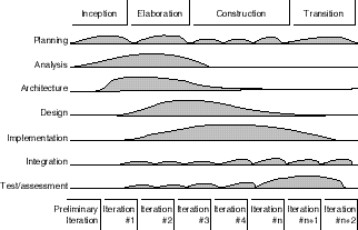
Figure 2: The Rational Unified Process
During the inception phase, you establish the business case for the system and delimit the project's scope. The business case includes success criteria, risk assessment, estimates of the resources needed, and a phase plan showing a schedule of major milestones. During inception, it's common to create an executable prototype that serves as a proof of concept. At the end of the inception phase, you examine the life-cycle objectives of the project and decide whether or not to proceed with full-scale development.
The goals of the elaboration phase are to analyze the problem domain, establish a sound architectural foundation, develop the project plan, and eliminate the highest risk elements of the project. Architectural decisions must be made with an understanding of the whole system. This implies that you describe most of the requirements of the system. To verify the architecture, you implement a system that demonstrates the architectural choices and executes significant use cases. At the end of the elaboration phase, you examine the detailed system objectives and scope, the choice of an architecture, and the resolution of major risks, and decide whether or not to proceed with construction.
During the construction phase, you iteratively and incrementally develop a complete product that is ready for transition to its user community. This implies describing the remaining requirements and acceptance criteria, fleshing out the design, and completing the implementation and test of the software. At the end of the construction phase, you decide if the software, the sites, and the users are all ready to go operational.
During the transition phase, you deploy the software to the user community. Once the system has been put into the hands of its end users, issues often arise that require additional development in order to adjust the system, correct some undetected problems, or finish some of the features that may be been postponed. This phase typically starts with a beta release of the system, which is then replaced with the production system. At the end of the transition phase, you decide whether or not the life cycle objectives of the project have been met, and possibly if you should start another development cycle. This is also a point where you wrap up the lessons learned on the project in order to improve your development process to be applied to the next project.
Each phase in the Unified Process can be further broken down into iterations. An iteration is a complete development loop resulting in a release (either internal or external) of an executable product constituting a subset of the final product under development, which then is grown incrementally from iteration to iteration to become the final system. Each iteration goes through the various process work flows, although with a different emphasis on each process work flow, depending upon the phase. During inception, the focus is on requirements capture. During elaboration, the focus turns to analysis and design. In construction, implementation is the central activity, and transition centers on deployment.
Going through the four major phases is called a development cycle, and results in one software generation. The first pass through the four phases is called the initial development cycle. Unless the life of the product stops, an existing product will evolve into its next generation by repeating the same sequence of inception, elaboration, construction, and transition phases. This is the evolution of the system, and so the development cycles following the initial development cycle are the evolution cycles.
Let's take these ideas about architecture and apply them to the order system.
This system is styled as a classic three-tiered architecture, as Figure 3 shows.
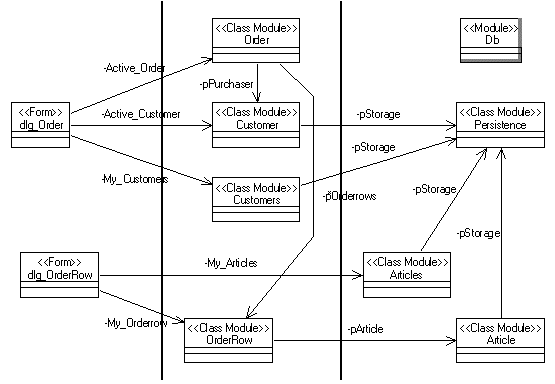
Figure 3. A three-tiered architecture
The system's user services are implemented by two forms, dlg_Order and dlg_OrderRow. These abstractions represent the actual forms that make up the system's user interface. Similarly, the system's data services are implemented by three class modules, Persistence, Article, and Articles. These abstractions, together with the module DB, provide the mechanisms necessary to store the order system's data in a persistent database. Finally, between these two layers, the system's business services are implemented by four class modules, Order, OrderRow, Customer, and Customers. These classes define the vocabulary of the order system's domain, and in addition encapsulate the business rules that shape the use of this vocabulary.
This architecture didn't just happen, of course. Rather, it was grown through the process described above.
Inception started with the building of prototypes for the order system's user interface. This not only helped identify the behavior we wanted in the system, but it also gave us a way to get rapid user feedback, to see if we were building the right system. This phase was largely driven by examining the order system's use cases. For example, one of the order system's use cases is Manage Order, where the flow of events is described as follows:
The use case starts when the Order Administrator has requested the system to display all orders. The system then shows a list of the current registered orders.
The Order Administrator can select (or deselect) at any time orders displayed in the list and do the following:
Creating a new order includes the following flow of events:
Customer
And for each order row:
Article type
Quantity
The other branches of this use case include a similar flow of events. Together, all the use cases of the order system make up its use-case view.
During elaboration, we established the order system's architecture. That's when we settled on the three-tier architecture as shown in Figure 3. This class diagram is part of the system's design view. Even with that architectural framework, there's enough for us to validate our design by trying it out against the use cases we defined during inception. There's also enough for us to begin construction of the executable system.
During construction, we grew our architecture by expanding each layer. For example, the details of the system's data services can be visualized by the class diagram shown in Figure 4, which is also part of the system's design view.
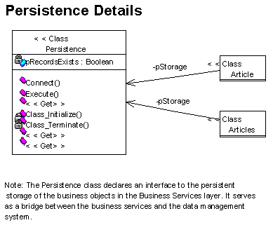
Figure 4. Data services class diagram
Similarly, we can visualize the system's business services by the class diagram shown in Figure 5.
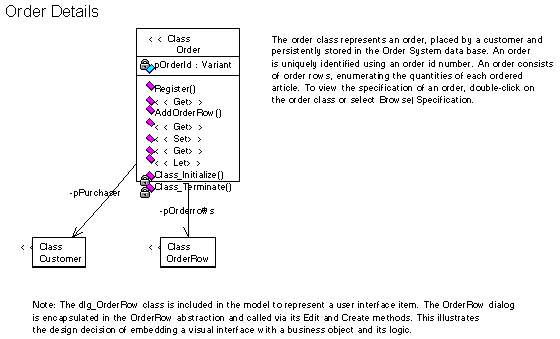
Figure 5. Business services class diagram
Finally, we can visualize the system's user services by the class diagram shown in Figure 6.
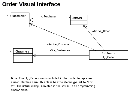
Figure 6: User services class diagram
The previous three diagrams are all part of the order system's design view. Collectively, they are important in visualizing, specifying, and documenting the logical architecture of the order system. As we begin to evolve this architecture into an executable system, we have to consider its physical architecture, which is described in the component diagram shown in Figure 7.
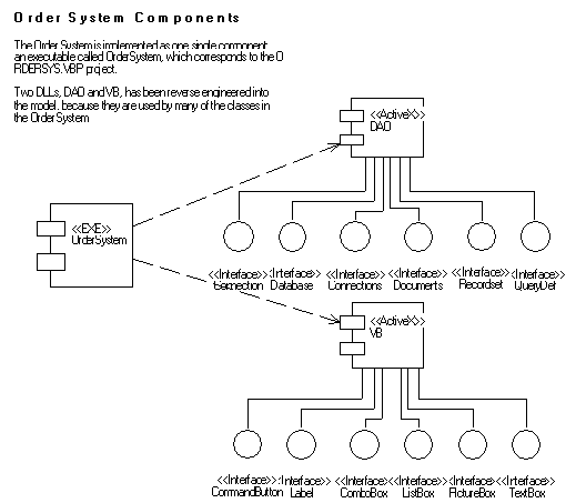
Figure 7: Component Diagram
As this figure shows, we've made the design decision to implement the order system as one executable that in turn builds upon two ActiveX® controls.
Successfully deploying a software-intensive system for the enterprise involves much more than sitting down and banging out piles of code. You have to build the right system, and that involves driving the development process with use cases. You have to build a resilient system, and that involves selecting the right architectural style. You have to grow your system, and that involves building it up iteratively and incrementally from a number of different views.
Even with the small example we've modeled above, it is clear that UML helps to visualize, specify, construct, and document a software-intensive system. Imagine, then, when you attack problems of much greater complexity, how much more important it is for you to model your system from different views using UML.
Object-oriented modeling languages started to appear sometime between the mid-1970s and the late 1980s as methodologists, faced with a new genre of object-oriented programming languages, began to experiment with alternative approaches to analysis and design. The number of object-oriented methods increased from less than 10 to more than 50 during the period between 1989 and 1994. Many users of these methods had trouble finding any one modeling language that met their needs completely, thus fueling the so-called "method wars." Learning from experience, new generations of these methods began to appear with a few clearly prominent methods emerging, most notably Grady Booch's Booch method, Ivar Jacobson's Object-Oriented Software Engineering (OOSE), and James Rumbaugh's Object Modeling Technique (OMT). Each of these was a complete method, although each was recognized as having certain strengths and weaknesses. In simple terms, the Booch method was particularly expressive during the design and construction phases of projects, OOSE provided excellent support for business engineering and requirements analysis, and OMT-2 was expressive for analysis and data-intensive information systems.
A critical mass of ideas started to form by the mid-1990s when Booch (Rational Software Corporation), Jacobson (Objectory), and Rumbaugh (General Electric) began to adopt ideas from each other's methods, which collectively were becoming recognized as the leading object-oriented methods worldwide. As the primary authors of the Booch, OOSE, and OMT methods, we were motivated to create a unified modeling language for three reasons. First, our methods were already evolving toward each other independently. It made sense to continue that evolution together rather than apart, eliminating the potential for any unnecessary and gratuitous differences that would further confuse users. Second, by unifying our methods, we could bring some stability to the object-oriented marketplace, allowing projects to settle on one mature modeling language and letting tool builders focus on delivering more useful features. Third, we expected that our collaboration would yield improvements in all three earlier methods, helping us to capture lessons learned and to address problems that none of our methods previously handled well.
As we began our unification, we established three goals to bound our work:
Devising a language for use in object-oriented analysis and design is not unlike designing a programming language. First, we had to constrain the problem: Should the language encompass requirements specification? Should the language be sufficient to permit visual programming? Second, we had to strike a balance between expressiveness and simplicity: too simple a language would limit the breadth of problems that could be solved, and too complex a language would overwhelm the mortal developer. In the case of unifying existing methods, we also had to be sensitive to the installed base: make too many changes, and we would confuse existing users; resist advancing the language, and we would miss the opportunity of engaging a much broader set of users and of making the language simpler. The UML definition strives to make the best trade-offs in each of these areas.
The UML effort started officially in October 1994 when Rumbaugh joined Booch at Rational. Our project's initial focus was the unification of the Booch and OMT methods. The version 0.8 draft of the Unified Method (as it was then called) was released in October 1995. Around the same time, Jacobson joined Rational and the scope of the UML project was expanded to incorporate OOSE. Our efforts resulted in the release of the UML version 0.9 documents in June 1996. Throughout 1996, we invited and received feedback from the general software engineering community. During this time, it also became clear that many software organizations saw UML as strategic to their business. We established a UML consortium with several organizations willing to dedicate resources to work toward a strong and complete UML definition. Those partners contributing to the UML 1.0 definition included Digital Equipment Corporation, Hewlett-Packard, i-Logix, Intellicorp, James Martin and Company, IBM, ICON Computing, MCI Systemhouse, Microsoft, Oracle, Rational, Texas Instruments, and Unisys. This collaboration resulted in UML version 1.0, a modeling language that was well defined, expressive and powerful, and applicable to a wide spectrum of problem domains. In response to their request for proposals, UML version 1.0 was offered for standardization to the Object Management Group (OMG) in January 1997.
Between January 1997 and July 1997, the original group of partners was expanded to include virtually all of the other submitters and contributors of the original OMG response, including Andersen Consulting, Ericsson, ObjecTime Limited, Platinum Technology, PTech, Reicht Technologies, Softeam, Sterling Software, and Taskon. A semantics task force was formed, led by Cris Kobryn of MCI Systemhouse and administered by Ed Eykholt of Rational, to formalize the UML specification and to integrate UML with other standardization efforts. A revised version of UML (version 1.1) was offered to the OMG for standardization in July 1997. In September 1997, this version was accepted by the OMG Analysis and Design Task Force (ADTF) and the OMG Architecture Board, and then put up for vote by the entire OMG membership. UML was accepted by the OMG on November 14, 1997.
Further information about UML can be found at the Rational Software Corporation Web site (http://www.rational.com/uml/index.shtml).
Note Portions of this article are excepted from The UML User's Guide, by Grady Booch, James Rumbaugh, and Ivar Jacobson (Menlo Park, California: Addison-Wesley Publishing Company, 1998).