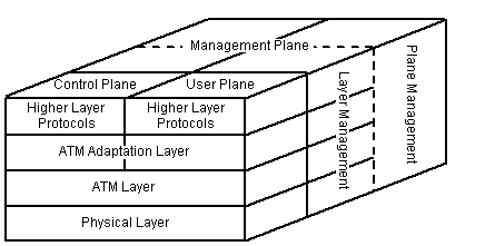
The ATM protocol reference model (PRM) consists of three planes: a user plane to transport user information, a control plane to manage signaling information, and a management plane to maintain the network and carry out operational functions. The management plane is further subdivided into layer management and plane management to manage the different layers and planes.
Protocols of the control plane and the user plane include the following layers: the physical layer, the ATM layer, and the ATM adaptation layer. The ATM model can also include other layers users might want to add in addition to those listed. The following graphic shows the ATM model.

The physical layer deals with physical medium issues such as voltage and bit timing. Because ATM has been designed to be independent of the transmission medium, it does not prescribe a specific set of rules, but rather it indicates that ATM cells may be sent on a wire or fiber by themselves or packaged inside the payload of other carrier systems.
The ATM layer deals with cells and their transport; it defines cell layout and the meaning of header fields. The ATM layer includes two interfaces: the user-network interface (UNI) and the network-network interface (NNI). The UNI defines the boundary between a host and an ATM network (or the customer and the carrier). The NNI refers to the line between two ATM switches. The header field varies slightly at the UNI and NNI. The following table illustrates the bit allocation of a cell header for the two interfaces.
Bit allocation |
|||||||
Function |
UNI |
NNI |
Role |
||||
|
General Flow Control (GFC) |
4 |
0 |
Used for physical access control. |
||||
|
Virtual Path Identifier (VPI) |
8 |
12 |
Indicates a virtual path identification number to distinguish cells from the same connection. |
||||
|
Virtual Circuit Identifier (VCI) |
16 |
16 |
Indicates a virtual circuit identification number to distinguish cells from the same connection. |
||||
Bit allocation |
|||||||
Function |
UNI |
NNI |
Role |
||||
|
Payload Type Identifier (PTI) |
3 |
3 |
Indicates the presence of user information and whether the given ATM cell experienced traffic congestion. |
||||
|
Cell Loss Priority (CLP) |
1 |
1 |
Indicates whether the corresponding byte may be discarded during a time of network congestion. |
||||
|
Header Error Control (HEC) |
8 |
8 |
Used for sensing and correcting errors. |
||||
The ATM layer also deals with establishing and releasing virtual circuits, described in the next section. The ATM layer provides a transparent connection, called the ATM connection, to the higher layer—an end-to-end connection is established by a concatenation of connection elements.
The two types of ATM connections are virtual circuits (VCs) and virtual paths (VPs). VC is a general term that signifies a logical unidirectional connection between two endpoints. ATM cells transported on a particular VC are associated by a common unique identifier referred to as a virtual circuit identifier (VCI). When a network connection is established, a route from the source computer to the destination computer is selected as part of the connection setup, and that route is used for all traffic flowing over the connection. An example of an end-to-end connection between two users, using only the VCI field of the ATM header, is presented next.
Suppose a virtual circuit consisting of a four-hop path is selected between two users, A and B, by a routing algorithm. After the network finds a path between the two nodes, it assigns the VCI values to be used at each node along the path and sets up routing tables at nodes N1 to N5. When the transmission starts, all cells of the connection follow the same path in the network. Once the communication is completed, one of the two end users releases the connection, and the VC is also terminated. The end-to-end connection defined by the concatenation of VC links is called a virtual circuit connection (VCC).
Virtual path (VP) is a generic term for a bundle of virtual circuit connections, all having the same VPI value and terminating at the same pair of endpoints. In ATM cells, a virtual path identifier (VPI) is assigned for each VP. When a VP is routed, all the VCs belonging to that VP are routed together.
The term virtual path connection (VPC) is used to refer to a sequential collection of VPs—VPC defines a route between the source and destination nodes.
The ATM adaptation layer (AAL) is composed of two sublayers, the convergence sublayer (CS), and the segmentation and reassembly (SAR) layer. The CS functions convert the user service information coming from the upper layer into a protocol data unit (PDU), and also carry out the opposite process.
The SAR layer segments PDUs to form the user data field of the ATM cell on the transmission side and puts them back together again at the destination side. The AAL's main function is to resolve any disparity between services provided by the ATM layer and the service requested by the user. The AAL adapts user service information with the ATM cell format and handles such issues as transmission error processing, misinserted or lost cell processing, flow control functions to meet the types of services demanded by the user, and timing control functions to restore the user signal.