OSI Reference Model
ISO developed a model called the Open Systems Interconnection (OSI) reference model. It is used to describe the flow of data between the physical connection to the network and the end-user application. This model is the best known and most widely used model to describe networking environments.

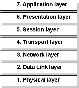
Figure 1.1 Open Systems Interconnection (OSI) Reference Model
As shown in Figure 1.1, the OSI layers are numbered from bottom to top. The most basic functions, such as putting data bits onto the network cable, are on the bottom, while functions attending to the details of applications are at the top.
In the OSI model, the purpose of each layer is to provide services to the next higher layer, shielding the higher layer from the details of how the services are actually implemented. The layers are abstracted in such a way that each layer believes it is communicating with the same layer on the other computer. In reality, each layer communicates only with adjacent layers on one computer. That is, for information to pass from Layer 5 on Computer A to Layer 5 on Computer B, it actually follows the route illustrated by Figure 1.2.

Figure 1.2 Communication Between OSI Layers
The following list describes the purpose of each of the seven layers of the OSI model and identifies services that they provide to adjacent layers.
- The Physical Layer addresses the transmission of the unstructured raw bit stream over a physical medium (that is, the networking cable). The Physical Layer relates the electrical/optical, mechanical, and functional interfaces to the cable. The Physical Layer also carries the signals that transmit data generated by all the higher layers.
This layer defines how the cable is attached to the network adapter card. For example, it defines how many pins the connector has and what each pin is used for. It describes the topology used to connect computers together (Token Ring, Ethernet, or some other). It also defines which transmission technique will be used to send data over the network cable.
- The Data Link Layer packages raw bits from the Physical Layer into data frames, which are logical, structured packets in which data can be placed. The exact format of the frame used by the network depends on the topology. That is, a Token Ring network data frame is laid out differently than an Ethernet frame. The Data Link Layer is responsible for providing the error-free transfer of these frames from one computer to another through the Physical Layer. This allows the Network Layer to assume virtually error-free transmission over the network connection. Frames contain source and destination addresses so that the sending and receiving computers can recognize and retrieve their own frames on the network.
- The Network Layer is responsible for addressing messages and translating logical addresses and names into physical addresses. This layer also determines the route from the source to the destination computer. It determines which path the data should take based on network conditions, priority of service, and other factors. It also manages traffic problems on the network, such as switching, routing, and controlling the congestion of data packets.
The Network Layer bundles small data frames together for transmission across the network. It also restructures large frames into smaller packets. On the receiving end, the Network Layer reassembles the data packets into their original frame structure.
- The Transport Layer takes care of error recognition and recovery. It also ensures reliable delivery of host messages originating at the Application Layer. Similar to how the Network Layer handles data frames, this layer repackages messages — dividing long messages into several packets and collecting small messages together in one packet — to provide for their efficient transmission over the network. At the receiving end, the Transport Layer unpacks the messages, reassembles the original messages, and sends an acknowledgment of receipt.
- The Session Layer allows two applications on different computers to establish, use, and end a connection called a session. This layer performs name recognition and the functions needed to allow two applications to communicate over the network, such as security functions.
The Session Layer provides synchronization between user tasks by placing checkpoints in the data stream. This way, if the network fails, only the data after the last checkpoint has to be retransmitted. This layer also implements dialog control between communicating processes, regulating which side transmits, when, for how long, and so on.
- The Presentation Layer determines the form used to exchange data between networked computers. It can be called the network's translator. At the sending computer, this layer translates data from a format received from the Application Layer into a commonly recognized, intermediary format. At the receiving end, this layer translates the intermediary format into a format useful to that computer's Application Layer.
The Presentation Layer also manages network security issues by providing services such as data encryption. It also provides rules for data transfer and provides data compression to reduce the number of bits that need to be transmitted.
- The Application Layer serves as the window for application processes to access network services. This layer represents the services that directly support the user applications such as software for file transfers, database access, and electronic mail.


