In the early years of networking, sending and receiving data across a network was confusing because large companies, such as IBM, Honeywell, and Digital Equipment Corporation had individual standards for connecting computers. The transmit and receive processes had to "talk" to the same protocols to communicate. It was unlikely that applications operating on different equipment from different vendors would be able to communicate. Vendors, users, and standards bodies needed to agree upon and implement a standard architecture that would allow computer systems to exchange information even though they were using software and equipment from different vendors.
In 1978, the International Standards Organization (ISO) introduced a model for Open Systems Interconnect (OSI) as a first step toward international standardization of the various protocols required for network communication. This ISO OSI model incorporates the following qualities.
Each layer of the OSI model exists as an independent module. In theory, you can substitute one protocol for another at any given layer without affecting the operation of layers above or below, although you probably wouldn't want to do so.
The principles used to create the seven-layer model are listed below.
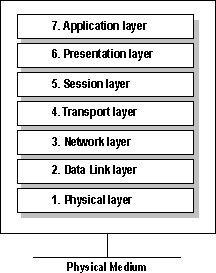
The following diagram shows the numbering of the layers, beginning with the physical layer, which is closest to the network media.

Figure 1.3 Layers of the OSI model
The physical layer is the lowest layer of the OSI model. This layer controls the way unstructured, raw, bit-stream data is sent and received over a physical medium. This layer describes the electrical or optical, mechanical, and functional interfaces to the physical network medium. The physical layer carries the signals for all of the higher layers.
Data-encoding modifies the simple, digital-signal pattern (1s and 0s) used by the computer to better accommodate the characteristics of the physical medium and to assist in bit and frame synchronization.
Data encoding resolves the following issues.
Physical medium attachment resolves the following issues.
The transmission technique determines whether the encoded bits will be transmitted by means of baseband (digital signaling or broadband (analog) signaling.
Physical-medium transmission determines whether it is appropriate to transmit bits as electrical or optical signals, based on the following criteria.
The data-link layer provides error-free transfer of data frames from one computer to another over the physical layer. The layers above this layer can assume virtually error-free transmission over the network.
The data-link layer provides the following functions.
The network layer controls the operation of the subnet. It determines which physical path the data takes, based on the network conditions, the priority of service, and other factors.
The network layer provides the following functions.
The network layer at the transmitting computer must build its header in such a way that the network layers residing in the subnet's intermediate systems can recognize the header and use it to route the data to the destination address.
This layer eliminates the need for higher layers to know anything about the data transmission or intermediate switching technologies used to connect systems. The network layer is responsible for establishing, maintaining, and terminating the connection to one or to several intermediate systems in the communication subnet.
In the network layer and the layers below it, the peer protocols are between each computer and its immediate neighbor, which is often not the ultimate destination computer. The source and destination computers may be separated by many intermediate systems.
The transport layer makes sure that messages are delivered in the order in which they were sent and that there is no loss or duplication. It removes the concern from the higher layer protocols about data transfer between the higher layer and its peers.
The size and complexity of a transport protocol depend on the type of service it can get from the network layer or data link layer. For a reliable network layer or data-link layer with virtual-circuit capability, such as NetBEUI's LLC layer, a minimal transport layer is required. If the network layer or data-link layer is unreliable or supports only datagrams (as TCP/IP's IP layer and NWLink's IPX layer do), the transport layer should include frame sequencing and acknowledgment, and associated error-detection and recovery.
Functions of the transport layer include the following tasks.
The transport layer can accept large messages, but there are strict size limits imposed by the layers at the network level and lower. Consequently, the transport layer must break up the messages into smaller units, called frames, and attach a header to each frame.
If the lower layers do not maintain sequence, the transport header (TH) must contain sequence information, which enables the transport layer on the receiving end to present data in the correct sequence to the next higher layer.
Unlike the lower subnet layers, whose protocols are between immediately adjacent nodes or computers, the transport layer and the layers above it are true source-to-destination layers. They are not concerned with the details of the underlying communications facility. Software for layers on the source computer at the transport level and above carries on a conversation with similar software on the destination computer, using message headers and control messages.
The session layer establishes a communications session between processes running on different computers, and can support message-mode data transfer.
Functions of the session layer include:
The presentation layer serves as the data translator for the network. This layer on the sending computer translates data from the format sent by the application layer into a common format. At the receiving computer, the presentation layer translates the common format to a format known to the application layer.
The presentation layer provides the following functions.
The application layer serves as the window for users and application processes to access network services. The application layer provides the following functions.
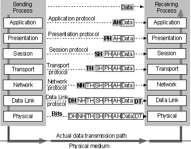
The OSI model presents a standard data flow architecture, with protocols specified in such a way that layer n at the destination computer receives exactly the same object as was sent by layer n at the source computer.

Figure 1.4 OSI model data flow
The sending process passes data to the application layer, which attaches an application header (AH) and then passes the frame to the presentation layer.
The presentation layer can transform data in various ways, if necessary, such as by translating it and adding a header. It then gives the result to the session layer. The presentation layer is not "aware" of which portion (if any) of the data received from the application layer is AH and which portion is actually user data, because that information is irrelevant to the presentation layer's role.
The process is repeated from layer to layer until the frame reaches the data-link layer. There, in addition to a header, a data trailer (DT) is added to aid in frame synchronization. The frame is then passed down to the physical layer, where it is actually transmitted to the receiving computer.
On the receiving computer, the various headers and the DT are stripped off one by one as the frame ascends the layers and finally reaches the receiving process.
Although the actual data transmission is vertical, each layer is programmed as if the transmission were horizontal. For example, when a sending transport layer gets a message from the session layer, it attaches a transport header (TH) and sends it to the receiving transport layer. The fact that the message actually passes to the network layer on its own machine is unimportant.
In addition to defining the ideal seven-layer architecture and the network functions allocated to each layer, the OSI model also defines a standard set of rules and associated terms that govern the interfaces between layers.
The active protocol elements in each layer are called entities, which are typically implemented by means of a software process. For example, the TCP/IP protocol suite contains two entities within its transport layer: Transmission Control Protocol (TCP) and User Datagram Protocol (UDP). Entities in the same layer on different computers are called peer entities.
The layer directly below layer-n entities implements services that will be used by layer n.
For data transfer services, OSI defines the terminology for the discrete data components passed across the interface and between peer entities, as described in the following example.

Figure 1.5 Vertical interface entities
Problems can occur in the data-flow path between two network stations. These problems can include errant, restricted, or even halted communication. Vertical and peer-trace utilities can be developed by third-party vendors to trace network communication errors.
Layer entities within a computer can call layer entities above and below them by means of established interface-call mechanisms (such as an interrupt in MS-DOS or, in Windows NT, an API-function call or IRP submission)and then pass a defined IDU structure. These call mechanisms provide the means to write a trace utility, which can do the following items.
If the data-flow problem is due to a layer entity's passing incorrect or incorrectly formatted ICI information, an examination of the log generated by the interface trace utility should reveal the cause of the problem. Vertical-interface trace utilities that can be used to troubleshoot networking include the NBTRAP (NetBIOS interface trace) utility for MS-DOS and the TDITRACE (Transport Driver Interface interface trace) utility for Windows NT, among others.
A specially configured computer can connect to the physical medium to receive and examine all frames sent to and from specified network addresses. The user can set the computer software to display frame-header information at any functional layer. The user can then view peer-protocol conversations between selected computers. If the data-flow problem is due to an error in the peer protocol, the user can detect it by examining the trace. Peer-protocol trace utilities include Sniffer from Network General and Microsoft Network Monitor, among others.

Figure 1.6 Troubleshooting, using a Data Flow Trace
Recognizing a need for standards in the local area network (LAN) market, the IEEE undertook Project 802. Named for the year (1980) and month (February) of its inception, Project 802 defines a family of low-level protocol standards at the physical and data-link layers of the OSI model.
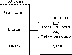
Under the terms of IEEE 802, the OSI data-link layer is further divided into two sublayers: Logical Link Control (LLC) and Media Access Control (MAC).

Figure 1.7 Comparison of IEEE layers and the OSI model
Data-link-layer functions allocated to the LLC sublayer include the following.
Data-link-layer functions allocated to the MAC sublayer include the following items.
Project 802 specifications include the following categories.
The low-level protocol specifications 802.3 CSMA/CD, 802.4 Token Bus, and 802.5 Token Ring differ at the physical layer and MAC sublayer, but are compatible at the LLC sublayer.
The 802 standards have been adopted by the following standards bodies.
Closely related to the IEEE 802 standards is a more recently developed low-level protocol standard, Fiber Distributed Data Interchange (FDDI). FDDI was developed by ANSI and is based on the use of fiber-optic cable.
FDDI differs from the IEEE 802 standards at the physical layer and MAC sublayer, but is compatible with the IEEE standards at the LLC sublayer.
Protocol entities within a network architecture provide various types of data-transfer services from a layer to the layers above it. The most prevalent data-transfer services are called reliable connection and unreliable connectionless.
A connection service requires a virtual circuit or connection to be established from the source computer to a single destination computer before any data transfer can take place. A connection acts like a tube: The sender pushes objects in at one end, and the receiver takes them out at the other end, in proper sequence. Because sequencing is provided, a message that is larger than the maximum transmit-frame size can be broken down into multiple frames, sent across the network, and re-sequenced at the receiving computer.
A connectionless service requires no initial connection and offers no guarantee that the data units will arrive in sequence. No connection is required, so messages can be sent to one or multiple destination stations. No sequencing is provided, so messages can be sent only in single-frame size.
A reliable service never loses data because the receiver acknowledges receipt of all data sent. If the sender doesn't receive acknowledgment, it re-sends.
With an unreliable service, no acknowledgments are sent, so there is no guarantee that data sent was ever received.
Microsoft network products require that the underlying network drivers provide both reliable-connection and unreliable-connectionless data-transfer services.
Microsoft network products use unreliable-connectionless data transfer only when there is a need to send data simultaneously to many stations. Often, unreliable-connectionless data transfer is used to locate the name of a computer. Once the computer name is received, reliable-connection data transfer is used to connect to the computer and complete the desired transaction. For example, an unreliable-connectionless data transfer may be sent to all computers in a domain (such as net send /d:<domain name> "hello") to find the name of a server that provides a particular service.
Different protocol entities offer different modes by which data can be transferred across the network from one process to another. As indicated in Table 1.1, some protocols, such as the NetBEUI NBFP, support more than one data-transfer mode.
Table 1.1 Data-transfer Mode Definitions and Protocols
Data-transfer mode |
|
|
|
Reliable connection | Message mode | Message delimination and synchronization | NetBEUI NBFP, TCP/IP NetBT, NWLink NBIPX |
Byte-stream mode | Byte granular data sequencing and acknowledgment | TCP/IP | |
Packetstream mode | Packet granular data sequencing and acknowledgment | NetBEUI, LLC, MSDLC, NWLink SPX | |
Unreliable connectionless | Datagram mode | NetBEUI NBFP and LLC;MSDLC, TCP/IP UDP and IP; NWLink IPX | |
The following sections discuss the attributes of various data-transfer modes.
When the sending client submits a larger-than-packet-size message to be sent, the sending protocol entity breaks the message into frame-sized segments. These include message-delimiter information in the protocol header, which identifies where the client submitted message starts and ends. This process allows the receiving-protocol driver to receive the entire client message before indicating the data to the receiving client.
If the receiving-client buffer fills up before the receiving-station protocol entity has received the entire message, it will still provide the partial message to the receiving client. It will also indicate that the data provided is a partial message and that the receiving client must supply another buffer to receive the remaining portion of the message.
When the receiving-protocol entity has received the entire message, it returns a message to the sending-protocol entity, acknowledging receipt of the entire message.
When the sending client submits a larger-than-packet-size message, the sending-protocol-driver entity breaks the message into segments but does not include message-delimiter information in the protocol header. The receiving-station-protocol entity provides the data to the receiving client when the receiving client provides the buffers to receive it, without any regard to the original message size.
When the receiving-protocol entity provides the data to the receiving client, it returns a byte acknowledgment to the sending-protocol entity, acknowledging receipt of all data up to a specified byte. The sending client can then begin sending the message at the last byte acknowledged.
In this mode, the sending client can submit only packet-size messages. The receiving protocol provides the packet-by-packet data in sequence to the receiving client.
While the receiving protocol entity provides a frame of data to the receiving client, it returns a message to the sending protocol entity, acknowledging receipt of all packets up to the specified packet number.
Note
The Windows Sockets emulator emulates message-mode data transfer over the NWLink SPX packet stream. The Sockets emulator component will break large messages into packets and place message delimiters in the packet stream. The receiving Sockets emulator will not provide the received data to the receiving Sockets client until the entire message has been received.
The sending client can submit only packet-size messages to be sent. If the data unit received is larger than the receiving client's next receive buffer, then as much of the received data unit as will fit is placed in the receiving client's buffer and provided to the client. The portion of the received data unit that could not fit in the client buffer is simply lost; no associated error is returned to the receiving client. If the data unit received is smaller than the client buffer, the protocol entity will place the received data unit in the client buffer and immediately provide the message, without waiting for more data to be received.
No acknowledgment is returned to the sending-protocol entity.
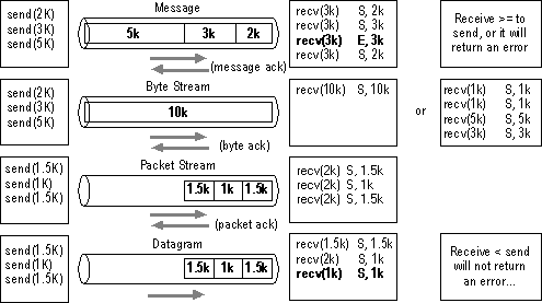
The following diagram illustrates the data transfer process: 'S' (on the right side of the diagram) indicates a SUCCESS return status code on the receive. 'E' indicates an error status on the receive: ERROR_MORE_DATA on message mode data transfer.

Figure 1.8 Data-transfer modes