Grid-fitting a glyph outline
The fundamental task of instructing a glyph is one of identifying the critical characteristics of the original design and using instructions to ensure that those characteristics will be preserved when the glyph is rendered at different sizes on different devices. Consistent stem weights, consistent color, even spacing, and the elimination of pixel dropouts are common goals.
To accomplish these goals, it is necessary to ensure that the correct pixels are turned on when a glyph is rasterized. It is the pixels that are turned on that create the bitmap image of the glyph. Since it is the shape of the glyph outline that determines which pixels will make up the bitmap image of that character at a given size, it is sometimes necessary to change or distort the original outline description to produce a high quality image. This distortion of the outline is known as grid-fitting.
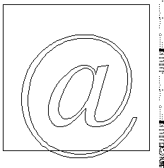
The figure below illustrates how grid-fitting a character distorts the outline found in the original design.
Figure 1-9 12 point outlines ungrid-fitted (left) and grid-fitted (right)

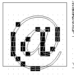
As the illustration above suggests, the grid-fitting employed in TrueType goes well beyond aligning a glyph's left side bearing to the pixel grid. This sophisticated grid-fitting is guided by instructions. The beneficial effects of grid-fitting are illustrated in the next figure.
Figure 1-10 12 point outlines and bitmap ungrid-fitted (left) and grid-fitted (right)

Grid-fitting is the process of stretching the outline of a glyph according to the instructions associated with it. Once a glyph is grid-fitted, the point numbers will be unchanged but the actual location of that point in the coordinate grid may have shifted. That is, the coordinates for a given point number will, very likely, have changed after a glyph is grid-fitted.
What are instructions?
The TrueType instruction set provides a large number of commands designed to allow designers to specify how character features should be rendered. Instructions are the mechanism by which the design of a character is preserved when it is scaled. In other words, instructions control the way in which a glyph outline will be grid-fitted for a particular size or device.
Instructing a font will reshape the outline for a given glyph at a specific size on a given target device in such a way that the correct pixels are included within its outline. Reshaping the outline means moving outline points. Points that have been acted upon by an instruction are said to have been touched. Note that a point need not actually be moved to be touched. It must simply be acted upon by an instruction. (See MDAP, chapter 3.)
TrueType fonts can be used with or without instructions. Uninstructed fonts will generally produce good quality results at sufficiently high resolutions and point sizes. The range of sizes over which an uninstructed font will produce good quality results depends not only on the output device resolution and point size of the character but also on the particular font design. The intended use of the font can also be a factor in determining whether or not a particular font should be instructed. For most fonts, if legibility of small point sizes on low resolution devices is important, adding instructions will be critical.
Instructing a font is a process that involves analyzing the key elements of a glyph's design and using the TrueType instruction set to ensure that they are preserved. The instructions are flexible enough to allow characteristics that are roughly the same to be "homogenized" at small sizes while allowing the full flavor of the original design to emerge at sizes where there are sufficiently many pixels.
How does the TrueType interpreter know the manner in which an outline should be distorted to produce a desirable result? This information is contained in instructions attached to each character in the font. Instructions specify aspects of a character's design that are to be preserved as it is scaled. For example, using instructions it is possible to control the height of an individual character or of all the characters in a font. You can also preserve the relationship between design elements within a character thereby ensuring, for example, that the widths of the three vertical stems in the lower case m will not differ dramatically at small sizes.
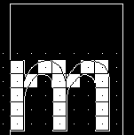
The following figure illustrates how changing a glyph's outline at a specific size will yield a superior result. They show that an uninstructed 9 point Arial lowercase m suffers the loss of a stem due to chance effects in the relationship of stems to pixel centers. In the second glyph, instructions have aligned the stems to the grid so that the glyph suffers no similar loss.
Figure 1-11 9 point Arial m—uninstructed (left), instructed (right)


The TrueType interpreter
This section describes the actions of the TrueType interpreter. It is the interpreter, as the name suggests, that "interprets" or carries out the instructions.
More concretely, the interpreter processes a stream or sequence of instructions. Typically these instructions take their arguments from the interpreter stack and place their results on that stack. The only exceptions are a small number of instructions that are used to push data onto the interpreter stack. These instructions take their arguments from the instruction stream.
All of the interpreter's actions are carried on in the context of the Graphics State, a set of variables whose values guide the actions of the interpreter and determine the exact effect of a particular instruction.
The interpreter's actions can be summarized as follows:
1. The interpreter fetches an instruction from the instruction stream, an ordered sequence of instruction opcodes and data. Opcodes are 1-byte in size. Data can consist of a single byte or two bytes (a word). If an instruction takes words from the instruction stream it will create those words by putting together two bytes. The high byte appears first in the instruction stream and the low byte appears second.
The following instruction stream is depicted as it will be shown in the examples that follow. Note that the pointer indicates the next instruction to be executed.
 2. The instruction is executed
If it is a push instruction it will take its arguments from the instruction stream.
Any other instruction will pop any data it needs from the stack. A pop is illustrated below.

Any data the instruction produces is pushed onto the interpreter stack. A push is illustrated below.

As the previous discussion indicates, the interpreter stack is a LIFO or last in first out data structure. An instruction takes any data it needs from the last item placed on the stack. The action of removing the top item from the stack is commonly termed a pop. When an instruction produces some result it pushes that result to the top of the stack where it is potential input to the next instruction.
The instruction set includes a full range of operators for manipulating the stack including operators for pushing items onto the stack, popping items from the stack, clearing the stack, duplicating stack elements and so forth.
The effect of execution depends on the values of the variables that make up the Graphics State.
The instruction may modify one or more Graphics State variables. In the illustration shown, the Graphics State variable rp0 is updated using a value taken from the interpreter stack.
 3. The process is repeated until there are no further instructions to be executed.
Using instructions
Instructions can appear in a number of places in the font file tables that make up a TrueType font. They can appear as part of the Font Program, the CVT Program, or as glyph data. Instructions appearing in the first two apply to the font as a whole. Those found in glyph data ('glyf') apply to individual glyphs within a font.
The Font Program
The Font Program consists of a set of instructions that is executed once, the first time a font is accessed by an application. It is used to create function definitions (FDEFs) and instruction definitions (IDEFs). Functions and instructions defined in the Font Program can be used elsewhere in the font file.
The CVT Program
The CVT Program is a sequence of TrueType instructions executed every time the point size or transformation change. It is used to make font wide changes rather than to manage individual glyphs. The CVT Program is used to establish the values in the Control Value Table.
The purpose of the Control Value Table or CVT is to simplify the task of maintaining consistency when instructing a font. It is a numbered list of values that can be referenced by either of two indirect instructions (MIRP and MIAP). CVT entries can be used to store values that need to be the same across a number of glyphs in a font. For example an instruction might refer to a CVT entry whose purpose is to regularize stem weights across a font.
Figure 1-12 Some sample CVT entries
Entry # | Value | Description |
0 | 0 | upper and lower case flat base (base line) |
1 | -39 | upper case round base |
2 | -35 | lower case round base |
3 | -33 | figure round base |
4 | 1082 | x-height flat |
5 | 1114 | x-height round overlap |
6 | 1493 | flat cap |
7 | 1522 | round cap |
8 | 1463 | numbers flat |
9 | 1491 | numbers round top |
10 | 1493 | flat ascender |
11 | 1514 | round ascender |
12 | 157 | x stem weight |
13 | 127 | y stem weight |
14 | 57 | serif |
15 | 83 | space between the dot and the i |
Instructions that refer to values in the CVT are called indirect instructions as opposed to the direct instructions which take their values from the glyph outline.
As part of the TrueType font file, the values in the CVT are expressed in FUnits. When the outlines are converted from FUnits to pixel units, values in the CVT are also converted.
When writing to the CVT you may use a value that is in the glyph coordinate system (using WCVTP) or you can use a value that is in the original FUnits (using WCVTF). The interpreter will scale all values appropriately. Values read from the CVT are always in pixels (F26Dot6).
The Storage Area
The interpreter also maintains a Storage Area consisting of a portion of memory that can be used for temporary storage of data from the interpreter stack. Instructions exist that make it possible to read the values of stored data and to write new values to storage. Storage locations range from 0 to n-1 where n is the value established in the maxStorage entry in the maxProfile table of the font file. Values are 32 bit numbers.
Figure 1-13 Some storage area entries
Address | Value |
0 | 343 |
1 | 241 |
2 | -27 |
3 | 4654 |
4 | 125 |
5 | 11 |
The Graphics State
The Graphics State consists of a table of variables and their values. All instructions act within the context of the Graphics State. Graphics State variables have default values as specified in Appendix B, "Graphics State Summary". Their values can be determined or changed using instructions.
The Graphics State establishes the context within which all glyphs are interpreted. All Graphics State variables have a default value. Some of these values can be changed in the CVT Program if desired. Whatever the default value, it will be reestablished at the start of interpretation of any glyph. In other words, the Graphics State has no inter-glyph memory. Changing the value of a Graphics State variable while processing an individual glyph will result in a change that remains in effect only for that glyph.


 2. The instruction is executed
If it is a push instruction it will take its arguments from the instruction stream.
Any other instruction will pop any data it needs from the stack. A pop is illustrated below.


 3. The process is repeated until there are no further instructions to be executed.