Points
Outline points are specified by their location in the coordinate grid and by whether they are on or off curve points. Managing a point means managing its position in space and its status as an on or off curve point. The interpreter uses zones and reference points to manage the set of points that comprise the current glyph and to refer to specific points within that set.
Zones
Any point the font scaler interpreter references is in one of two zones, that is one of two sets of points that potentially make up a glyph description. The first of these referenced zones is zone 1 (Z1) and always contains the glyph currently being interpreted.
The second, zone 0 (Z0), is used for temporary storage of point coordinates that do not correspond to any actual points in the glyph in zone 1. Zone 0 is useful when there is a need to manipulate a point that does not exist on the glyph or if you need to remember an intermediate point position. (This is the twilight zone.)
The profile table establishes the maximum number of twilight points. These are numbers 0 through maxTwilightPoints -1 and are all set to the origin. These points can be moved in the same manner as any of the points in zone 1.
Points in zone 0 are moved to useful positions by using the MIAP and MIRP instructions and setting gep0 to point to Z0. Frequently, it is useful to set points in Z0 to key metric positions for the font.
Zone pointers
Three zone pointers, gep0, gep1 and gep2 are used to reference either of zone 0 or zone 1. Initially, all three zone pointers will point to zone 1.
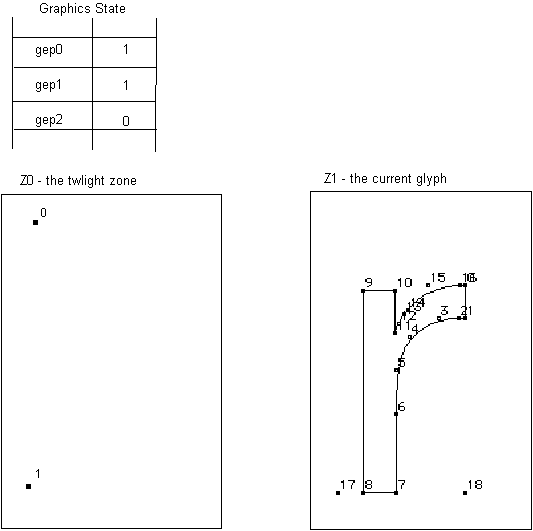
Figure 2–1 gep0 and gep1 point to zone 1 (the current glyph), gep2 points to zone 0 (the twilight zone)

Reference points
Zone pointers provide access to a group of points. Reference points provide access to specific points within the group. The interpreter uses three numbered reference points: rp0, rp1, and rp2. Each can be set to a number corresponding to any of the outline points in the glyph in zone 1 or any of the points in zone 0.
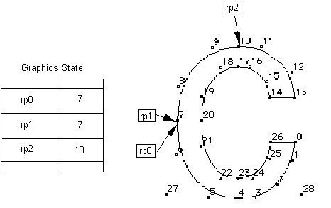
As shown in the following figure, two different reference points can refer to the same outline point.
Figure 2–2 A glyph pointed to by all three reference points

Collectively the zone pointers and reference points belong to the Graphics State. Their values can be altered using instructions. Many TrueType instructions rely on the graphics zone pointers and the reference points to fully specify their actions.
Phantom points
The font scaler will always add two "phantom points" to the end of every outline. If the entire set of contours for a glyph requires "n" points (i.e., contour points numbered from 0 to n-1), then the scaler will add points n and n+1. These points will be placed on the character baseline. Point "n" will appear at the character origin, while "n+1" will be placed at the advance width point.
Both points (n and n+1) may be controlled by TrueType instructions, with corresponding effects on the sidebearings and advance width of the instructed glyph. The side bearings and advance width that are computed using these phantom points are called the device-specific widths (since they reflect the results of grid fitting the width along with the glyph to the characteristics of the device). The device-specific widths can be different from or identical to the linearly scaled widths (obtained by simple scaling operations), depending on the instructions applied to the phantom points.

