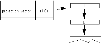

Figure 3–4 Setting the value of the Graphics State variable projection_vector
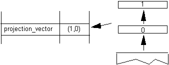
Code range | 0x00 - 0x01 |
a | 0: set vectors to the y-axis |
1: set vectors to the x-axis | |
Pops | – |
Pushes | – |
Sets | projection_vector |
freedom_vector |


Code range | 0x02 - 0x03 |
a | 0: set the projection_vector to the y-axis |
1: set the projection_vector to the x-axis | |
Pops | – |
Pushes | – |
Sets | projection_vector |

Code range | 0x04 - 0x05 |
a | 0: set the freedom_vector to the y-axis |
1: set the freedom_vector to the x-axis | |
Pops | – |
Pushes | – |
Sets | freedom_vector |

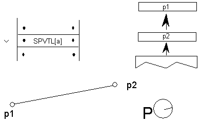
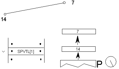
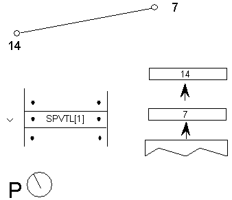
Code Range | 0x06 - 0x07 |
a | 0: sets projection_vector to be parallel to line segment from p1 to p2 |
1: sets projection_vector to be perpendicular to line segment from p1 to | |
Pops | p1: point number (ULONG) |
p2: point number (ULONG) | |
Pushes | – |
Uses | point p1 in the zone pointed at by zp2 |
point p2 in the zone pointed at by zp1 | |
Sets | projection_vector |

Code Range | 0x08 - 0x09 |
a | 0: set freedom_vector to be parallel to the line segment defined by points p1 and p2 |
1: set freedom_vector perpendicular to the line segment defined by points p1 and p2; the vector is rotated counter clockwise 90 degrees | |
Pops | p1: point number (ULONG) |
p2: point number (ULONG) | |
Pushes | – |
Sets | freedom_vector |
Uses | point p1 in the zone pointed at by zp2 point p2 in the zone pointed at by zp1 |
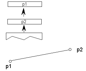
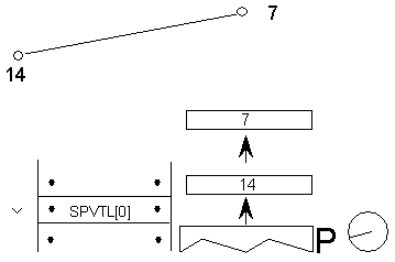
If parallel the freedom_vector points from p1 toward p2 as shown.

If perpendicular the freedom_vector is obtained by rotating the parallel vector in a counter clockwise manner as shown.

Code | 0x0E |
Pops | – |
Pushes | – |
Sets | freedom_vector |


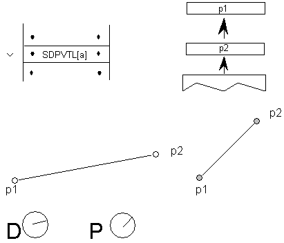
Code Range | 0x86 - 0x87 |
a | 0: Vectors are parallel to line |
1: Vectors are perpendicular to line | |
Pops | p1: first point number (ULONG) |
p2: second point number (ULONG) | |
Pushes | – |
Sets | dual_projection_vector and projection_vector |
Uses | point p1 in the zone pointed at by zp2 |
point p2 in the zone pointed at by zp1 |
Note:
The dual_projection_vector is set parallel to the points as they appeared in the original outline before any grid-fitting took place.
Code Range | 0x0A |
Pops | y: y component of projection_vector (2.14 fixed point number padded with zeroes) |
x: x component of projection_vector (2.14 fixed point number padded with zeroes) | |
Pushes | – |
Sets | projection_vector |
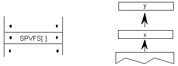
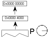
SFVFS[ ]
Code | 0x0B |
Pops | y: y component of freedom_vector (2.14 fixed point number padded with zeroes) |
x: x component of freedom_vector (2.14 fixed point number padded with zeroes) | |
Pushes | – |
Sets | freedom_vector |
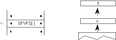
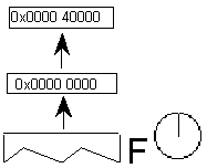
Code Range | 0x0C |
Pops | – |
Pushes | x: x component of projection_vector (2.14 fixed point number padded with zeroes) |
y : y component of projection_vector (2.14 fixed point number padded with zeroes) | |
Gets | projection_vector |


Note:
0x2D41 is the hex equivalent of  . As a result of this instruction, the projection_vector is set to a 45 degree angle relative to the x-axis.
Code Range | 0x0D |
Pops | – |
Pushes | x: x-component of freedom_vector (2.14 number padded with zeroes) |
y: y component of freedom_vector (2.14 number padded with zeroes) | |
Gets | freedom_vector |

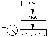
Code Range | 0x10 |
Pops | p: point number (ULONG) |
Pushes | – |
Sets | rp0 |
Affects | IP, MDAP, MIAP, MIRP, MSIRP, SHC, SHE, SHP |

Code Range | 0x11 |
Pops | p: point number (ULONG) |
Pushes | – |
Sets | rp1 |
Affects | IP, MDAP, MDRP, MIAP, MSIRP, SHC, SHE, SHP |

Code Range | 0x12 |
Pops | p:point number (ULONG) |
Pushes | – |
Sets | rp2 |

Code Range | 0x13 |
Pops | n: zone number (ULONG) |
Pushes | – |
Sets | zp0 |
Affects | ALIGNPTS, ALIGNRP, DELTAP1, DELTAP2, DELTAP3, IP, ISECT, MD, MDAP, MIAP, MIRP, MSIRP, SHC, SHE, SHP, UTP |

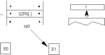
Code Range | 0x14 |
Pops | n: zone number (ULONG) |
Pushes | – |
Sets | zp1 |
Affects | ALIGNRPTS, ALIGNRP, IP, MD, MDRP, MSIRP, SHC, SHE, SHP, SFVTL, SPVTL |

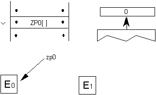
Code Range | 0x15 |
Pops | n: zone number (ULONG) |
Pushes | – |
Sets | zp2 |
Affects | ISECT, IUP, GC, SHC, SHP, SFVTL, SHPIX, SPVTL, SC |

Code Range | 0x16 |
Pops | n: zone number (ULONG) |
Pushes | – |
Sets | zp0, zp1, zp2 |
Affects | ALIGNPTS, ALIGNRP, DELTAP1, DELTAP2, DELTAP3, GC, IP, ISECT, IUP, MD, MDAP, MDRP, MIAP, MIRP, MSIRP, SC, SFVTL, SHPIX, SPVTL, SHC, SHE, SHP, SPVTL, UTP |

Code Range | 0x19 |
Pops | – |
Pushes | – |
Sets | round_state |
Affects | MDAP, MDRP, MIAP, MIRP, ROUND |
Uses | freedom_vector, projection_vector |
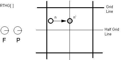
Code Range | 0x18 |
Pops | – |
Pushes | – |
Sets | round_state |
Affects | MDAP, MDRP, MIAP, MIRP, ROUND |
Uses | freedom_vector, projection_vector |
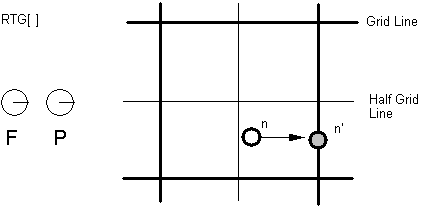
Code Range | 0x3D |
Pops | – |
Pushes | – |
Sets | round_state |
Affects | MDAP, MDRP, MIAP, MIRP, ROUND |
Uses | freedom_vector, projection_vector |
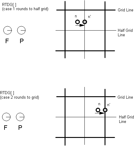
Code Range | 0x7D |
Pops | – |
Pushes | – |
Sets | round_state |
Affects | MDAP, MDRP, MIAP, MIRP, ROUND |
Uses | freedom_vector, projection_vector |
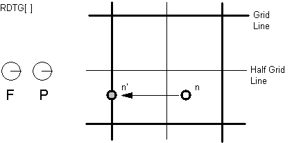
Code Range | 0x7C |
Pops | – |
Pushes | – |
Sets | round_state |
Affects | MDAP, MDRP, MIAP, MIRP, ROUND |
Uses | freedom_vector, projection_vector |
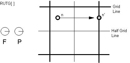
Code Range | 0x7A |
Pop | – |
Pushes | – |
Sets | round_state |
Affects | MDAP, MDRP, MIAP, MIRP, ROUND |
Uses | freedom_vector, projection_vector |
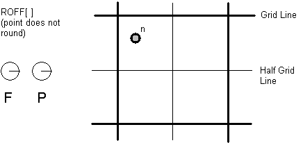
Code Range | 0x76 |
Pops | n: number decomposed to obtain period, phase, threshold |
Pushes | – |
Sets | round_state |
Affects | MDAP, MDRP, MIAP, MIRP, ROUND |


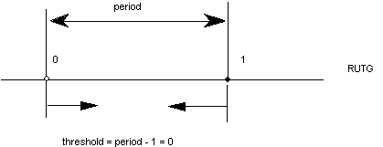
0 | period = gridPeriod/2 |
1 | period = gridPeriod |
2 | period = gridPeriod*2 |
3 | Reserved |
0 | phase = 0 |
1 | phase= period/4 |
2 | phase = period/2 |
3 | phase = gridPeriod*3/4 |
0 | threshold = period -1 |
1 | threshold = -3/8 * period |
2 | threshold = -2/8 * period |
3 | threshold = -1/8 * period |
4 | threshold = 0/8 * period |
5 | threshold = 1/8 * period |
6 | threshold = 2/8 * period |
7 | threshold =3/8 * period |
8 | threshold = 4/8 * period |
9 | threshold = 5/8 * period |
10 | threshold = 6/8 period |
11 | threshold = 7/8 * period |
12 | threshold = 8/8 * period |
13 | threshold = 9/8 * period |
14 | threshold = 10/8 * period |
15 | threshold = 11/8 * period |

Code Range | 0x77 |
Pops | n: ULONG decomposed to obtain period, phase, threshold (ULONG) |
Pushes | – |
Sets | round_state |
Affects | MDAP, MDRP, MIAP, MIRP, ROUND |
Code Range | 0x17 |
Pops | n: value for loop Graphics State variable (integer) |
Pushes | – |
Sets | loop |
Affects | ALIGNRP, FLIPPT, IP, SHP, SHPIX |

Code Range | 0x1A |
Pops | distance: value for minimum_distance (F26Dot6) |
Pushes | – |
Sets | minimum_distance |

Code Range | 0x8E |
Pops | s: selector flag (int32) |
value: USHORT (padded to 32 bits) used to set value of instruction_control. | |
Pushes | – |
Sets | instruction_control |
Selector flag 1 is used to inhibit grid-fitting. If s=1, valid values for the value argument are 0 (FALSE) and 1 (TRUE). If the value argument is set to TRUE (v=1), any instructions associated with glyphs will not be executed. For example, to inhibit grid-fitting when a glyph is being rotated or stretched, use the following sequence on the preprogram: | ||
PUSHB[000] 6 | /* ask GETINFO to check for stretching or rotation */ | |
GETINFO[] | /* will push TRUE if glyph is stretched or rotated */ | |
IF[] | /* tests value at top of stack */ | |
PUSHB[000] 1 | /* value for INSTCTRL */ | |
PUSHB[000] 1 | /* selector for INSTCTRL */ | |
INSTRCTRL[] | /* based on selector and value will turn grid-fitting off */ | |
EIF[] | ||
Selector flag 2 is used to establish that any parameters set in the CVT program should be ignored when instructions associated with glyphs are executed. These include, for example, the values for scantype and the CVT cut-in. If s=1, valid values for the value argument are 0 (FALSE) and 2 (TRUE). If the value argument is set to TRUE (v=2), the default values of those parameters will be used regardless of any changes that may have been made in those values by the preprogram. If the value argument is set to FALSE (v=0), parameter values changed by the CVT program will be used in glyph instructions. | ||
| ||
Code Range | 0x85 |
Pops | n: flags indicating when to turn on dropout control mode (16 bit word padded to 32 bits) |
Pushes | – |
Sets | scan_control |
Bit | Meaning if set |
8 | Set dropout_control to TRUE if other conditions do not block and ppem is less than or equal to the threshold value. |
9 | Set dropout_control to TRUE if other conditions do not block and the glyph is rotated. |
10 | Set dropout_control to TRUE if other conditions do not block and the glyph is stretched. |
11 | Set dropout_control to FALSE unless ppem is less than or equal to the threshold value. |
12 | Set dropout_control to FALSE unless the glyph is rotated. |
13 | Set dropout_control to FALSE unless the glyph is stretched. |
14 | Reserved for future use. |
15 | Reserved for future use. |
0x0000 | No dropout control is invoked |
0x01FF | Always do dropout control |
0x0A10 | Do dropout control if the glyph is rotated and has less than 16 pixels per-em |
Code Range | 0x8D |
Pops | n: 16 bit integer |
Pushes | – |
Sets | scan_control |
Rule 1 | If a pixel's center falls within the glyph outline, that pixel is turned on. |
Rule 2 | If a contour falls exactly on a pixel's center, that pixel is turned on. |
Rule 3 | If a scan line between two adjacent pixel centers (either vertical or horizontal) is intersected by both an on-Transition contour and an off-Transition contour and neither of the pixels was already turned on by rules 1 and 2, turn on the left-most pixel (horizontal scan line) or the bottom-most pixel (vertical scan line). This is "Simple" dropout control. |
Rule 4 | Apply Rule 3 only if the two contours continue to intersect other scan lines in both directions. That is, do not turn on pixels for 'stubs.' The scanline segments that form a square with the intersected scan line segment are examined to verify that they are intersected by two contours. It is possible that these could be different contours than the ones intersecting the dropout scan line segment. This is very unlikely but may have to be controlled with grid-fitting in some exotic glyphs. |
Rule 5 | If a scan line between two adjacent pixel centers (either vertical or horizontal) is intersected by both an on-Transition contour and an off-Transition contour and neither of the pixels was already turned on by rules 1 and 2, turn on the pixel which is closer to the midpoint between the on-Transition contour and off-Transition contour. This is "Smart" dropout control. |
Rule 6 | Apply Rule 5 only if the two contours continue to intersect other scan lines in both directions. That is, do not turn on pixels for 'stubs.' |
Code Range | 0x1D |
Pops | n: value for cut_in (F26Dot6) |
Pushes | – |
Sets | control_value_cut_in |
Affects | MIAP, MIRP |

Code Range | 0x1E |
Pops | n: value for single_width_cut_in (F26dot6) |
Pushes | – |
Sets | single_width_cut_in |
Affects | MIAP, MIRP |

Code Range | 0x1F |
Pops | n: value for single_width_value (FUnits) |
Pushes | – |
Sets | single_width_value |

Code Range | 0x4D |
Pops | – |
Pushes | – |
Sets | auto_flip |
Affects | MIRP |

Code Range | 0x4E |
Pops | – |
Pushes | – |
Sets | auto_flip |
Affects | MIRP |

Code Range | 0x7E |
Pops | weight: value for angle_weight |
Pushes | – |
Sets | angle_weight |

Code Range | 0x5E |
Pops | n: value for the delta_base (ULONG) |
Pushes | – |
Sets | delta_base |
Affects | DELTAP1, DELTAP2, DELTAP3, DELTAC1, DELTAC2, DELTAC3 |

Code Range | 0x5F |
Pops | n: value for the delta_shift (ULONG) |
Pushes | – |
Sets | delta_shift |
Affects | DELTAP1, DELTAP2, DELTAP3, DELTAC1, DELTAC2, DELTAC3 |
