Determining distances
At the lowest level, instructing a glyph means managing the distances between points. The first step in managing a distance is often one of determining its magnitude. For example, the first step in setting up the Control Value Table involves measuring the distances between key points in a font. Measuring the distance between two points in a glyph outline, while not difficult, must take into account certain factors.
All distance measurements are made parallel to the projection_vector, a unit vector whose direction will be indicated by a radius of a circle. Distances are projected onto this vector and measured along it. Distances have a direction that reflects the direction of the vector.
Measurements can refer to the distance between points in the original character outline or between points in the grid-fitted outline. The instruction that measures distances (MD) takes a Boolean value which determines whether distances will be measured on the original outline or in the grid-fitted outline.
Additionally, the TrueType interpreter distinguishes between three different types of distances: black, white, and grey. Certain instructions (MDRP, MIRP, ROUND) require that you specify a distance type.
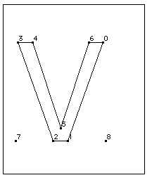
Black distances cross only black areas; white distances, white areas; and grey distances a combination of the two. In the following illustration, examples of black, white, and grey distances are shown. The distance [2,1] is black; [3,0] is grey and [4,6] is white.
Figure 2–3 White, black and grey distances

The distance type is used in determining how the ROUND and instructions that use the round_state will work with different output devices. For gray distances, rounding is unaffected. Black or white distances, however, require a compensation term be added or subtracted before rounding takes place. The amount of compensation needed will be set by the device driver. For example, if a printing engine has large pixels, the interpreter will compensate by shrinking black distances and growing white distances. Gray distances, because they combine black and white distances, will not change.
When the distance between two points is determined, the distance is always measured in the direction specified by the projection_vector. Similarly, when a point is moved, the distance it is moved will be measured along the projection_vector. When thinking about how the interpreter will project a distance, you may find it convenient to imagine that distances are projected onto a ruled line that is parallel to the projection vector.
In the example shown, distances are measured along a line that is parallel to the projection_vector. The distance from point 1 to point 2 must be projected onto the projection_vector (that is a line parallel to the projection_vector) before being measured. Since the line from point 1 to point 3 is parallel to the vector, the projection of the distance can be thought of as simply the line from 1 to 3. Since the projection of the line from point 4 to point 1 is perpendicular to the vector, the distance from point 4 to point 1 is zero despite the fact that the points do not coincide.

The vector can be set in any direction desired. In a simple case, the projection vector might be set to measure distance in the x-direction. In such a case, the vector is parallel to the x-axis. Similarly to measure distance in the y-direction, the projection_vector must be parallel to the y-axis.
To determine the distance between two points when the projection_vector points in the positive x-direction, one need only take the difference between their x coordinates. For example, the distance between the points (2, 1) and (7, 5) will be 5 units. Similarly, if the projection_vector pointed in the positive y-direction, the distance between the points would be 4 units.
Note that because the projection_vector has a direction, distances have a sign. Positive distances are those that are measured with the projection_vector. Negative distances are those that are measured against the projection_vector.
In the following example, the projection_vector points east (in the direction of the positive x-axis). The distance between points 1 and 2 is positive when measured from west to east (from point 1 to point 2). It is negative when measured from east to west (from point 2 to point 1).
Figure 2–4 Measuring the distance between two points

In many cases, it is convenient to disregard the sign associated with a distance. When the auto_flip Graphics State variable is set to TRUE, the sign of CVT entries will be changed when needed to match the sign of the actual measurement. This makes it possible to control distances measured with or against the projection_vector with a single CVT entry.


