7.3. Mixed configuration Example
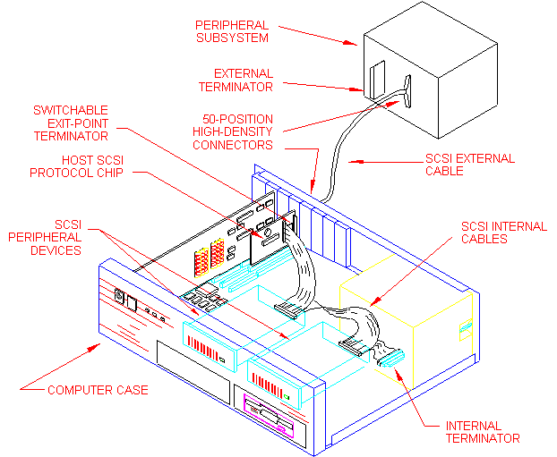
Figure 4 illustrates a mixed configuration with an add-in SCSI design alternative. This figure is provided as a reference and should not be construed as a specification of requirements. The internal terminator should be as close as possible to the last internal SCSI peripheral device; the distance in the figure is exaggerated for clarity. The system combines internal and external devices on the same SCSI bus.
 Figure 4 - Mixed Configuration Example
 Figure 4 - Mixed Configuration Example