Dennis Crain
Microsoft Developer Network Technology Group
May 1995
Click to open or copy the files in the DragBez sample application for this technical article.
This article describes the exercise of creating a C++ base class that permits interactive drawing of two endpoints and a Bezier curve connecting them. The motivation for creating the class was a desire to draw electrical connectors and cables within an application. Although the result does not look like electrical connectors and cables, the CCables base class is implemented in such a way that the drawing functions are easily overridden to permit more realistic drawing. The class is useful where there is any need to draw two visual objects connected by a curve. Microsoft® Win32® sample code is provided for the class and an application that utilizes the class.
So there I am, just minding my own business, reading the latest post from the Jag-lovers (Jag as in Jaguar the car) list server in Perth, Australia. This wiry little guy with a British accent comes up to me and says, "Dennis, I am writing a cool application that would look even cooler if the user interface included some nifty 3-D wire cables that plugged into gnarly-looking BNC or RCA connectors." Intently looking at him, I replied, "Sounds great. When are you going to write that code?" To which he replied, "This sounds right up your alley, Dennis." I knew that was coming! To humor him, I let him describe his vision with me. After all, I was reading mail about British cars and he is British.
Well, you've probably guessed the rest of the story. Why else would I be writing this article? However, I envisioned a group effort on this project. I agreed to provide the first part, a C++ class that would provide a means of drawing two endpoints and a curve between them in 2-D. Doesn't sound very exciting, does it. Well, I got a bit excited over it. It was fun and really turns out to be quite useful. For instance, suppose you wanted to draw data-flow diagrams and the connections between them (one of my favorite things to do in my spare time!). You could simply take my code, throw it in your application, and draw data-flow diagrams to your heart's content.
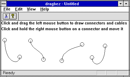
In addition to describing how I wrote the C++ class (CCables), I will show you how to modify the position of the endpoints (connectors) on the fly from within the calling class. Still not excited? How about a picture? If that doesn't get you interested, I suggest that you probably don't have a use for this topic.

Figure 1. Sample connectors and cables
At conception, the CCables class was to provide a means for drawing two connectors and then drawing the cable between them. I selected the name CCables to suggest the use of the class to simulate an electrical cable situated between two electrical connectors (albeit the final product looks nothing like electrical connectors and cables). The connectors are represented by ellipses, and the cable is a Bezier curve. Of course, the functions that draw these elements are virtual and can be overridden. As the class evolved, I provided member functions to permit hit-testing of the connectors, to control the shape of the control polygon (for the Bezier curve), and to provide information about the connectors. The best place to start is in the CCABLES.H file.
The essential elements of the CCables class are a pair of connectors and a cable connecting them. Everything else is provided to properly render and query them. Three data members define the relationship between the two connectors and the cable between them.
The nice thing about sample code is that you don't need to be quite as flexible as would be required in production code. This is a terrific excuse to let you know that this class deals with a single curve with two endpoints. Consistent with the connector metaphor, the endpoints are called m_FirstConnector and m_SecondConnector. They are CPoint objects as illustrated below.
CPoint m_FirstConnector;
CPoint m_SecondConnector;
The cable is drawn as a Bezier curve. The only data member required for the curve is an array of control points as shown below. NUMCONTROLPTS is an enumerated type with a value of 4. I will discuss how these points are generated later, in the discussion of the implementation of the class.
POINT m_CtrlPts[NUMCONTROLPTS];
As mentioned above, other data members are used to render and maintain the relationships between the connectors and the cable. Many of these data members are flags or symbols such as the following:
const DWORD FIRSTCONNECT;
const DWORD SECONDCONNECT;
enum   {NUMCONTROLPTS = 4};
enum   {BADQUAD, QUAD1, QUAD2, QUAD3, QUAD4};
enum   {CONNECTORRADIUS = 7};
enum   {HITTESTRECTS = 2};
The first two const DWORD variables are used as flags in the OnDrawConnector and OnDrawCable functions. Notice that after the two const DWORDs, several enumerated types are defined as well. Before I continue, I need to vent my feelings regarding the use of enumerated types versus the use of constants.
If you read my last article, "MFC: I'll Never Use It!", you know that I am new to C++. As such, I am accustomed to using the preprocessor to define various symbols that I need for use in my programs. So, my include files generally include lots of the following:
#define FIRSTCONNECT  1
#define SECONDCONNECT 2
Being a good engineer, I took a C++ class and was told that I should use constants instead of #define to ensure type safety. So I did this with two flags used in the DrawConnector function:
const DWORD FIRSTCONNECT;
const DWORD SECONDCONNECT;
The only problem I have with this is that I must now initialize them in the constructor, and copy constructor member initialization lists as follows:
CCables::CCables(const CCables& ccables) : FIRSTCONNECT (0x0001),
                                           SECONDCONNECT(0x0002)
{
...
}
Although I like the prospect of type safety and the ability to see these symbols in my debugger, I really don't like how cluttered this could get. What if I had 300 flags and bitmasks? What a mess that would be! I have left these constants in the class just to demonstrate the use of a member initialization list. However, my preference is to use enumerated types.
Using enumerated types, I would have defined the above two flags in the following manner in the include file:
enum {FIRSTCONNECT = 0x0001, SECONDCONNECT = 0x0002};
In my opinion, this is very straightforward and less error prone. Note that I use several enumerated types in the class. The only other alternative was to continue using #define. Having looked at lots of C++ code around Microsoft, I have found that the use of enumerated types is common. Unfortunately, so is the use of #define.
OK, off the soap box!
The enumerated types (shown below again for convenience) are used for 1) the number of POINT structures in an array for the Bezier curve; 2) determining the direction of the mouse gesture away from the mouse click that determines the location of the first connector; 3) the radius of the ellipses used to draw the connectors; and 4) the number of CRects in an array used to track hit-testing areas over the connectors.
enum   {NUMCONTROLPTS = 4};
enum   {BADQUAD, QUAD1, QUAD2, QUAD3, QUAD4};
enum   {CONNECTORRADIUS = 7};
enum   {HITTESTRECTS = 2};
Finally, the following data members are used for 1) tracking the relative position of the mouse gesture from the mouse click that determines the first connector; 2) the orientation of the gesture away from the first connector (see #2 above); and 3) the rectangles associated with the connectors for hit-testing.
int    m_GestureLimit;
int    m_GestureOrient;
CRect  m_Hittest[HITTESTRECTS];
The following code is CCABLES.H in its entirety. Public functions include OnDrawConnector, OnDrawCable, SetConnectorPoint, SetGestureLimit, GetConnectorPoint, and HittestConnector. An assignment operator and copy constructor are also provided. Two protected functions, SetControlPoints and GetGestureOrientation, are provided to assign the endpoints and the control polygon of the Bezier curve (the cable), and to determine the orientation of the control polygon, respectively.
class CCables : public CObject
{
// Operations.
public:
  CCables();
  virtual ~CCables();
  CCables& CCables::operator=(const CCables & ccables);
  CCables::CCables(const CCables& ccables);
  BOOL HittestConnector(CPoint point);
  CPoint GetConnectorPoint(int nConnectorNum);
  void SetConnectorPoint(CPoint point, int nConnectorNum,
                         CRect *prectHittest = NULL);
  virtual BOOL SetGestureLimit(CPoint point);
  virtual BOOL OnDrawConnector(CDC *pdc, int nConnectorNum);
  virtual BOOL OnDrawCable(CDC *pdc, int nViewLandmarks);

protected:
  void SetControlPoints();
  void GetGestureOrientation(CPoint XY0, CPoint XY1);

// Attributes.
public:
  const DWORD FIRSTCONNECT;
  const DWORD SECONDCONNECT;

protected:
  enum   {NUMCONTROLPTS = 4};
  enum   {BADQUAD, QUAD1, QUAD2, QUAD3, QUAD4};
  enum   {CONNECTORRADIUS = 7};
  enum   {HITTESTRECTS = 2};
  CPoint m_FirstConnector;
  CPoint m_SecondConnector;
  POINT  m_CtrlPts[NUMCONTROLPTS];
  int    m_GestureLimit;
  int    m_GestureOrient;
  CRect  m_Hittest[HITTESTRECTS];
};
Let's take a look at the implementation of the CCables class in three different areas. First we'll look at the class essentials, such as the constructor, destructor, copy constructor, and assignment operator. Then we will explore the two core functions of the class, SetConnectorPoint and SetGestureLimit, and the functions that support them. Finally we will briefly discuss the two virtual functions used to draw the connectors and cable, OnDrawConnector and OnDrawCable.
The class essentials include the constructor, destructor, assignment operator, and copy constructor.
The only thing unusual about the constructor is that awkward member initialization list (as discussed above). The m_GestureOrient variable is set to the BADQUAD enumerated type to simply establish the fact that the gesture orientation needs to be established (in the GetGestureOrientation function).
CCables::CCables() : FIRSTCONNECT(0x0001), SECONDCONNECT(0x0002)
{
  m_GestureOrient = BADQUAD;
}
The destructor does nothing special.
So why did I have to include an assignment operator? Why wouldn't the default assignment operator work? After all, there is nothing complex going on during assignment, as you can see in the following code.
CCables& CCables::operator=(const CCables& ccables)
{
  m_FirstConnector = ccables.m_FirstConnector;
  m_SecondConnector = ccables.m_SecondConnector;
  memcpy(&m_CtrlPts, &ccables.m_CtrlPts, NUMCONTROLPTS * sizeof(POINT));
  m_GestureLimit = ccables.m_GestureLimit;
  m_GestureOrient = ccables.m_GestureOrient;
  memcpy(&m_Hittest, &ccables.m_Hittest, HITTESTRECTS * sizeof(CRect));
  return *this;
}
As it turns out, the problem was not a problem at all, rather a "feature" to protect over-zealous programmers. If you look in AFX.H at the definition of CObject, you will find the assignment operator override has been made private. This effectively disables default assignment. A nearby comment in AFX.H indicates that this is to force compiler errors versus unexpected behavior. Talk about inconvenient! However, when you think about it, this makes perfect sense. After all, default assignment could be deadly if you are dynamically allocating memory in your class derived from CObject.
In the CObject class, the copy constructor is also private. Note in the following code that the copy constructor must also include the member initialization list found with the constructor.
CCables::CCables(const CCables& ccables) : FIRSTCONNECT(0x0001),
                                           SECONDCONNECT(0x0002)
{
  m_FirstConnector = ccables.m_FirstConnector;
  m_SecondConnector = ccables.m_SecondConnector;
  memcpy(&m_CtrlPts, &ccables.m_CtrlPts, NUMCONTROLPTS * sizeof(POINT));
  m_GestureLimit = ccables.m_GestureLimit;
  m_GestureOrient = ccables.m_GestureOrient;
  memcpy(&m_Hittest, &ccables.m_Hittest, HITTESTRECTS * sizeof(CRect));
}
So just what are the core functions? They are the functions that must be called before you can successfully draw the connectors and the cable. The core functions are SetConnectorPoint and SetGestureLimit. These functions call SetControlPoints and GetGestureOrientation, respectively.
The prototype for this function is:
BOOL CCables::SetConnectorPoint(CPoint point, int nConnectorNum,
                                CRect *prectHittest = NULL);
This function performs two tasks. One task is that of saving the rectangular area around the connector to be used as an area for subsequent hit-testing of the connector. If the prectHittest parameter is non-NULL, that rectangle becomes the area for hit-testing that particular connector. If this parameter is NULL, the rectangle is calculated based on the location of the connector and the CONNECTORRADIUS constant.
However, the most important task of the function is to assign the locations of the two connectors to the m_FirstConnector and m_SecondConnector member variables. The variable for which the assignment is to operate on is determined by the const DWORD flags discussed earlier, FIRSTCONNECT and SECONDCONNECT. The following code illustrates this process.
BOOL CCables::SetConnectorPoint(...)
{
...
    if (nConnectorNum == (int)FIRSTCONNECT)
      m_FirstConnector = point;
    else
    {
      m_SecondConnector = point;
      SetControlPoints();
    }
...
};
Notice that the SetControlPoints function is called after assigning a value to m_SecondConnector.
The prototype for this function is:
void SetControlPoints();
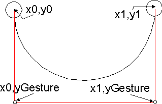
This function assigns the appropriate values to an array of points, m_CtrlPts. Appropriate values are those values that form the control polygon for the Bezier curve to be drawn later. Figure 2 illustrates the geometry of the control polygon.

Figure 2. Control polygon for drawing of Bezier curve to represent cable
The points x0,y0 and x1,y1 correspond to the m_FirstConnect and m_SecondConnect data members. Gesture corresponds to the m_GestureLimit data member. But you don't know anything about the gesture limit yet. So let's continue with the SetGestureLimit function.
The prototype for this function is:
virtual BOOL SetGestureLimit(CPoint point);
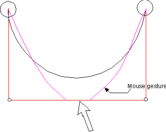
In the above discussion of the SetControlPoints function, I mentioned the m_GestureLimit data member. The value assigned to this data member is the distance, in the y direction, of the second and third control points from the endpoints. An example of a "gesture" is mouse movement as shown in Figure 3.

Figure 3. Mouse gesture that determines y offset for control polygon (purple line represents arc of mouse movement)
As shown in the following code, m_GestureLimit is the y component of the CPoint object passed to the function. The assignment is slightly different depending on the orientation of the mouse movement away from the origin of the connector. If the movement is out of the first or second quadrant of the connector, the y component is decreasing—hence the conditional statement m_GestureLimit = (point.y <= m_GestureLimit) ? point.y : m_GestureLimit. If the movement is out of the third for fourth quadrant, the y component is increasing. In this case the assignment is based on the condition statement m_GestureLimit = (point.y > m_GestureLimit) ? point.y : m_GestureLimit.
BOOL CCables::SetGestureLimit(CPoint point)
{
    if (m_GestureOrient == BADQUAD)
      GetGestureOrientation(m_FirstConnector, point);

    switch (m_GestureOrient)
    {
      case QUAD1:
      case QUAD2:
        m_GestureLimit = (point.y <= m_GestureLimit) ? point.y : m_GestureLimit;
        break;
      case QUAD3:
      case QUAD4:
        m_GestureLimit = (point.y > m_GestureLimit) ? point.y : m_GestureLimit;
        break;
      default:
        break;
    }
    return TRUE;
}
However, before these assignments can be made, the direction of the mouse movement away from the connector must be known. That is why, in the code above, a call to GetGestureOrientation precedes the switch statement in which the assignment of m_GestureLimit takes place.
The prototype for this function is:
void CCables::GetGestureOrientation(CPoint XY0, CPoint XY1);
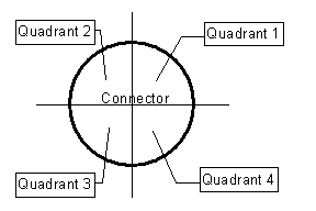
This purpose of this function is to determine the direction of the mouse gesture away from the first endpoint (connector). Figure 4 illustrates the four directions considered relevant to the implementation of GetGestureOrientation.

Figure 4. Four directions of mouse gesture away from connector
To detect the direction in which the mouse is moving, two points are compared. If x1 is greater than x0, the two candidate directions are quadrants 1 and 4. If x1 is less than x0, the two candidates are quadrants 2 and 3. In the following code, notice that if there is no movement in the x or y direction (BADQUAD), the gesture limit is set to y0 and the function returns. This takes care of the special case where the mouse down and mouse up events occur at the same point.
void CCables::GetGestureOrientation(CPoint XY0, CPoint XY1)
{
  if ((XY1.x - XY0.x == BADQUAD) || (XY1.y - XY0.y == BADQUAD))
  {
    m_GestureLimit = XY0.y;
    return;
  }
// Detect quadrant.
  m_GestureOrient = (XY1.x >= XY0.x)
                    ? ((XY1.y >= XY0.y) ? QUAD4 : QUAD1)
                    : ((XY1.y > XY0.y) ? QUAD3 : QUAD2);
  m_GestureLimit = XY0.y;
}
Two functions, OnDrawConnector and OnDrawCable, are called to draw the connectors and cable, respectively. Each function is virtual to let you draw the connector and cable components as you see fit. The following discusses the base implementation of these functions.
The connector is drawn as an ellipse. The bounding rectangle for the ellipse is the previously determined rectangle used for hit-testing (in the SetConnectorPoint function). The function selects a NULL brush into the DC so that the interior of the ellipse is transparent.
BOOL CCables::OnDrawConnector(CDC *pdc, int nConnectorNum)
{
  ASSERT (pdc);
  BOOL bRet = FALSE;
  // Draw connector based on hittest rect.
  if (pdc)
  {
    // Get the appropriate hittest rect.
    CRect rectDraw = (nConnectorNum & FIRSTCONNECT) ? m_Hittest[0]
                                                    : m_Hittest[1];
    CBrush *pBrush = new(CBrush);
    pBrush->CreateStockObject(NULL_BRUSH);
    CBrush *OldBrush = pdc->SelectObject(pBrush);
    pdc->Ellipse((LPRECT)rectDraw);
    pdc->SelectObject(OldBrush);
    delete pBrush;
    bRet = TRUE;
  }
  return bRet;
}
This function draws the cable as a Bezier curve, using the control points previously determined and set in the SetConnectorPoint function. In addition, the control polygon may be drawn if the nViewLandmarks parameter has a value greater than or equal to 1. The control points are copied to an array of points and passed to the GDI PolyLine function. Ellipses are used to draw the second and third control points for clarity. Note the use of a red solid pen for drawing the polyline.
BOOL CCables::OnDrawCable(CDC *pdc, int nViewLandmarks)
{
  ASSERT (pdc);
  BOOL bRet = FALSE;

  if (pdc)
  {
    if (pdc->PolyBezier((const POINT *)&m_CtrlPts, NUMCONTROLPTS))
      bRet = TRUE;

    if (nViewLandmarks)
    {
      POINT points[4];
      points[0].x = m_CtrlPts[0].x;
      points[0].y = m_CtrlPts[0].y;
      points[1].x = m_CtrlPts[1].x;
      points[1].y = m_CtrlPts[1].y;
      points[2].x = m_CtrlPts[2].x;
      points[2].y = m_CtrlPts[2].y;
      points[3].x = m_CtrlPts[3].x;
      points[3].y = m_CtrlPts[3].y;

      CPen cpen(PS_SOLID, 1, RGB(0xFF, 0x00, 0x00));
      CPen *cpOldPen = pdc->SelectObject(&cpen);
      // Draw control polygon.
      pdc->Polyline((LPPOINT)&points, 4);
      pdc->SelectObject(cpOldPen);
      cpen.DeleteObject();
      // Draw 2nd and 3rd control points.
      pdc->Ellipse(m_CtrlPts[1].x-2, m_CtrlPts[1].y-2,
                   m_CtrlPts[1].x + 2, m_CtrlPts[1].y + 2);
      pdc->Ellipse(m_CtrlPts[2].x -2, m_CtrlPts[2].y -2,
                   m_CtrlPts[2].x + 2, m_CtrlPts[2].y + 2);
    }
  }
  return bRet;
}
The DragBez sample interactively utilizes the CCables class. I used the application wizard to create DragBez. It is a single-document interface (SDI) application. The user uses the left mouse button to click and drag the cable in the desired direction. When the user releases the left mouse button, the second connector and the cable are drawn. To reposition the connectors and cables, the user clicks a connector (using the right mouse button) and drags the connector to a new position.
The action all takes place in the mouse event handlers in the view class (in the DRAGBVW.CPP file). In addition to discussing how the CCables class is used, I will discuss how I used the CList template.
DragBez has two relevant left mouse events—left mouse down and left mouse up. Left mouse events create new connectors and cables.
The sequence of events begins with a left mouse down event. When this event takes place, the OnLButtonUp function is called. This function simply allocates a CCables object (m_pCables) and calls CCable::SetConnectorPoint and CCable::OnDrawConnector as described above. Note that the object is not deleted in this function. It will be used later and added to a list of CCables objects.
void CDragbezView::OnLButtonDown(UINT nFlags, CPoint point)
{
    CDC *pdc = GetDC();
    // If m_pCables, then user probably released Lbutton outside of
    // client area, so delete dangling pointer.
    if (m_pCables)
      delete(m_pCables);
    m_pCables = new(CCables);
    m_bGestureSet = FALSE;
    if (m_pCables && pdc)
    {
      m_pCables->SetConnectorPoint(point, m_pCables->FIRSTCONNECT);
      m_pCables->OnDrawConnector(pdc, m_pCables->FIRSTCONNECT);
      ReleaseDC(pdc);
    }
}
When the user releases the left mouse button, the OnLButtonUp event handler is called. The location at which this takes place is assumed to be the location of the second connector. Accordingly, CCable::SetConnectorPoint is called, using the SECONDCONNECT flag. The connector is drawn by calling CCable::OnDrawConnector. Then the cable is drawn by a call to CCable::OnDrawCable. Finally, the CCable object is added to a list of objects.
void CDragbezView::OnLButtonUp(UINT nFlags, CPoint point)
{
   CDC *pdc = GetDC();
   if (m_pCables && pdc)
   {
     if (!m_bGestureSet)
       m_bGestureSet = m_pCables->SetGestureLimit(point);
     m_pCables->SetConnectorPoint(point, m_pCables->SECONDCONNECT);
     m_pCables->OnDrawConnector(pdc, m_pCables->SECONDCONNECT);
     m_pCables->OnDrawCable(pdc, m_ViewLandmarks);
     // Add the ccable object.
     m_connectorlist.AddTail(*m_pCables);
     delete(m_pCables);
     m_pCables = NULL;
     ReleaseDC(pdc);
   }
}
DragBez acts upon two right mouse events—right mouse down and right mouse up. Right mouse events modify connectors and cable locations.
When a right mouse down event occurs, the list of previously drawn connectors is traversed. As the list is traversed, the location of the right mouse down event is compared to the hit-test rectangle (in the CCable::HittestConnector function) that is part of each CCable object in the list. If the right mouse point is within the hit-test rectangle, success is assumed and the traversal of the list stops. The point associated with the connector is then retrieved by calling CCable::GetConnectorPoint. This point is assigned to m_OldMousePos. Why the old mouse position? Well, remember, right mouse events are used to modify the position of the connectors.
void CDragbezView::OnRButtonDown(UINT nFlags, CPoint point)
{
    POSITION pos;
    pos = m_connectorlist.GetHeadPosition();
    while (pos) {
      m_pos = pos;
      m_PickedCable = m_connectorlist.GetNext(pos);
      if ((m_nConnector = m_PickedCable.HittestConnector(point)))
      {
        m_bConnectorHit = TRUE;
        m_OldMousePos = m_PickedCable.GetConnectorPoint(m_nConnector);
        m_szHitPointDiff = m_OldMousePos - point;
        break;
      }
      else
      {
        m_bConnectorHit = FALSE;
      }
    }
}
It is assumed that when the user releases the right mouse button, the location at which that takes place will become the new location of the connector. So, the list is updated with the CCable object in its current state.
void CDragbezView::OnRButtonUp(UINT nFlags, CPoint point)
{
    if (m_pos)
    {
      m_connectorlist.SetAt(m_pos, m_PickedCable);
      InvalidateRect(NULL);
    }
    else
      MessageBeep(0);
}
But something is missing here. How is the position information within the object getting updated? This is happening in the mouse move handler, OnMouseMove.
The OnMouseMove function handles mouse movement while the left or right mouse button is depressed. Recall that these two states correspond to the general observation that the left mouse button is involved in the creation of connectors and the cable, and the right mouse button is associated with the modification of existing connectors and cables.
During mouse movement with the left mouse button depressed, CCable::SetGestureLimit is called. You may recall that this function is one of the core functions of the CCables class; it is used to assign the y component of the second and third control points for the Bezier curve used to represent the cable.
void CDragbezView::OnMouseMove(UINT nFlags, CPoint point)
{
    if (nFlags & MK_LBUTTON)
    {
      if (m_pCables)
        m_bGestureSet = m_pCables->SetGestureLimit(point);
    }
    if (nFlags & MK_RBUTTON)
      ...
}
When the right mouse button is depressed during mouse movement, things become a bit more complicated. After making sure that a connector was successfully hit-tested, the ROP code is changed to R2_NOT, the old connector and cable are drawn, the new connector position is set in the object (by a call to CCable::SetConnectorPoint), and the connectors and cable are drawn. The following code illustrates these steps.
void CDragbezView::OnMouseMove(UINT nFlags, CPoint point)
{
    if (nFlags & MK_LBUTTON)
      ...
    if (nFlags & MK_RBUTTON)
    {
      if (m_bConnectorHit && m_pos)
      {
        CDC *pdc = GetDC();
        if (pdc)
        {
          DWORD nConnect = (m_nConnector & m_PickedCable.FIRSTCONNECT)
                            ? m_PickedCable.FIRSTCONNECT
                            : m_PickedCable.SECONDCONNECT;
          int oldrop = pdc->SetROP2(R2_NOT);
          m_PickedCable.SetConnectorPoint(m_OldMousePos, nConnect);
          m_PickedCable.OnDrawConnector(pdc, nConnect);
          m_PickedCable.OnDrawCable(pdc, m_ViewLandmarks);
          point.Offset(m_szHitPointDiff);
          m_PickedCable.SetConnectorPoint(point, nConnect);
          m_PickedCable.OnDrawConnector(pdc, nConnect);
          m_PickedCable.OnDrawCable(pdc, m_ViewLandmarks);
          m_OldMousePos = point;
          pdc->SetROP2(oldrop);
          ReleaseDC(pdc);
        }
      }
    }
}
I used the CList template for the list of CCable objects. To create a list, I included the following in the public section of DRAGVW.H:
CList <CCables, CCables&> m_connectlist
It was all very straightforward and convenient. However, I did run into a problem that was not addressed in any of the documentation that I encountered. I needed to provide my own assignment operator. You may recall my earlier discussion about this. CList is derived from CObject. If you look in AFX.H at the definition of CObject, you will find the assignment operator override has been made private. This disables default assignment. So, it is just a simple matter of providing an assignment operator in your own class derived from CObject.
The CCable class started out as an exercise to create electrical connectors and cables for use in a co-worker's application. This article describes the creation of the base class for doing this. Although the resultant connectors and cables look nothing like electrical connectors and cables, the base class is very useful should you need to have any two visual objects connected by a curved line (represented by a Bezier curve). Perhaps my co-worker will use the class as a base for his 3DCCables class!