Dennis Crain
Microsoft Developer Network Technology Group
Created: April 30, 1994
Click to open or copy the files in the MYGL sample application for this technical article.
OpenGL, an industry-standard three-dimensional software interface, is now a part of Microsoft® Windows NT™ version 3.5. As a hardware-independent interface, the operating system needs to provide pixel format and rendering context management functions. Windows NT provides a generic graphics device interface (GDI) implementation for this as well as a device implementation. This article details these implementations, OpenGL/NT functions, and tasks that applications need to accomplish before OpenGL commands can be used to render images on the device surface.
We all knew that it was just a matter of time before three-dimensional (3-D) graphics would become part of a Microsoft operating system. Well, it finally happened. Version 3.5 of Microsoft® Windows NT™ now includes OpenGL (OpenGL/NT). So just what is OpenGL? Originally developed by Silicon Graphics, Inc., it is an industry-standard procedural software interface for producing 3-D graphics. It does so by providing roughly 120 commands to draw various primitives including points, lines, and polygons in various modes. With OpenGL, you can create high-quality still and animated 3-D color images. So now you are an OpenGL expert, right? If you feel that you don’t qualify for that distinction, go to the bookstore and pick up the OpenGL Programming Guide and the OpenGL Reference Manual. Both are authored by the OpenGL Architecture Review Board. They are required reading if you plan to use OpenGL. (For the ISBN numbers for these manuals, see the "Bibliography" section at the end of this article.)
This article is for anyone who has an interest in OpenGL/NT. Whether you have been writing OpenGL programs for years or are just getting started, this article is for you. OpenGL is a hardware-independent 3-D interface. Because of this, it does not include commands for the initialization and management of devices’ display surfaces. This is the responsibility of the operating system within which you find OpenGL. So you can see that, irrespective of OpenGL experience, anyone new to OpenGL/NT needs to understand the details of the implementation specific to Windows NT. At this point, your hopes may have been dashed. You may have been looking for an article that describes how to create 3-D images. Don’t become too depressed. Future articles will deal with this, but, as some say, "You need to learn to walk before you run." Everyone using OpenGL/NT needs to understand how to get the 3-D images on the device surface.
This article will frequently discuss pixel format and rendering context management. Successfully managing these tasks provides the connection between the hardware independence of OpenGL/NT. Two mechanisms are provided in Windows NT to provide this connection to OpenGL—pixel format manipulation APIs and WGL APIs. WGL APIs provide a mechanism for managing the OpenGL rendering context.
MYGL is a sample OpenGL/NT application written in C++ using the Microsoft Foundation Class Library (MFC). A class, COpenGL, wraps the WGL and pixel format APIs and also provides numerous utility functions for OpenGL/NT applications. Code samples used in this article are taken from MYGL. The MYGL user interface permits you to specify and set the pixel format of a window (MYGL is an SDI [single-document interface] application), enumerate the pixel formats, and query the current pixel format properties.
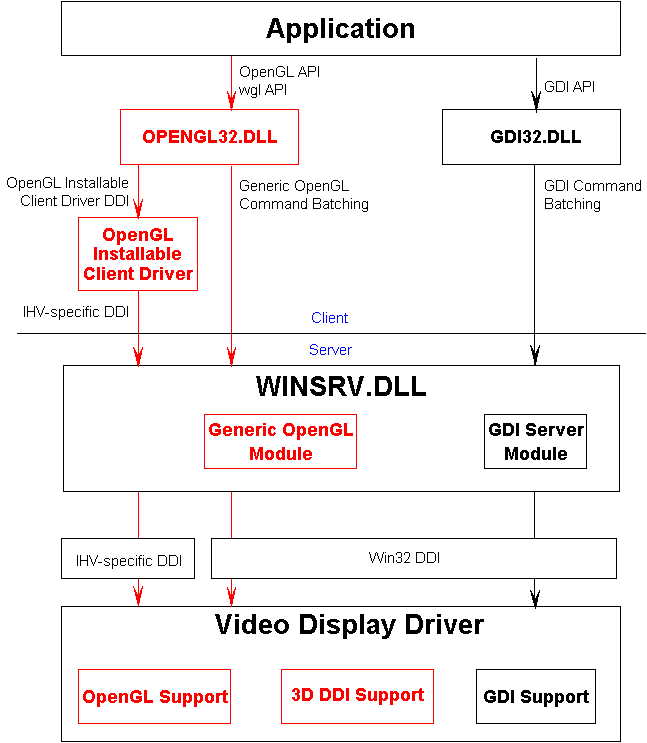
It is always helpful to understand the architecture of a new feature. From an application developer’s perspective, a good understanding of the architecture eases the application development process. Design and implementation decisions can be made with intelligence instead of confusion. If you buy that, take a look at Figure 1. It is the infamous architecture diagram with an OpenGL/NT flavor this time.


Figure 1. OpenGL/NT architecture
As you work through this section, don’t worry if you don’t understand everything. Much of what is discussed briefly will be discussed in detail later. You might want to return to this section periodically as you progress through the article.
If you have a machine like mine (a true antique), OpenGL applications use the generic format. All of the pixel format management, double buffering, and rendering context management is handled by the generic OpenGL module and GDI. If you have a machine with a sophisticated video display adapter and a video display driver that supports OpenGL/NT, you are indeed fortunate. I’m sure I could round up several dozen Dr. GUI T-shirts if you want to consider a trade!
More seriously, OpenGL/NT calls are intercepted by the installable client driver. The client driver packages these OpenGL and WGL commands and sends them to the video display driver. The video display driver is linked with libraries that contain dispatch functions, OpenGL code, and some portable low-level drawing support functions. The big win with OpenGL support in the video driver and appropriate hardware is speed. Rendering can be accelerated tremendously. Figure 2 broadly illustrates the differences between generic and device formats.
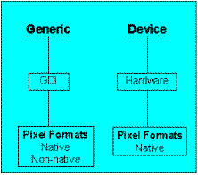
Figure 2. Generic and device formats
To illustrate the difference between the generic and device formats a bit more, let’s discuss the new pixel format API, DescribePixelFormat.
DescribePixelFormat obtains pixel format information about a given device. This information includes values such as the number of color bitplanes, the type of pixel data, and so on (pixel format will be discussed in more detail later). An application calls DescribePixelFormat (found in GDI32.DLL). In the generic format, DescribePixelFormat takes the pixel format index and races through roughly 300 lines of code, filling in a PIXELFORMATDESCRIPTOR structure based on the index. The function then returns the maximum number of generic pixel formats available. In the device format, the pixel format index is compared to the number of device formats (if any). If the pixel format is determined to be a device-supported format, the driver function, DrvDescribePixelFormat, is called. After returning from the driver, DescribePixelFormat returns the sum of the generic formats and the device formats.
A discussion of the generic format would not be complete without mentioning its limitations. The following list of limitations is taken from the Windows NT OpenGL Help file:
An application cannot directly print an OpenGL image to a monochrome printer. There is, however, a workaround for this situation. An application can directly print an OpenGL image to a color printer that offers four or more bits of color information per pixel.
An application can draw both OpenGL graphics and GDI graphics directly into a single-buffered window, but not into a double-buffered window.
Windows NT has a single system hardware color palette, which applies to the whole screen. An OpenGL window cannot have its own hardware palette. It can have its own logical palette. To do so, it must become a palette-aware application.
A window with OpenGL graphics does not directly support these Windows NT capabilities. There are workarounds, however, for working with the Clipboard.
The Inventor class library, built on top of OpenGL, provides higher-level constructs for programming 3-D graphics. It is not included in version 1.0 of Windows NT OpenGL.
There is, however, support for several ancillary buffers: stencil buffer, accumulation buffer, back buffer (double buffering), and depth (z-axis) buffer.
The OpenGL frame buffer is nothing more than the sum of all the buffers utilized by OpenGL. These include color buffers, depth buffer, stencil buffer, and an accumulation buffer. Color buffers contain pixel data that is either color indexed (don’t interpret this as "Windows palette") or RGBA values (A, or alpha, is used as a measure of opacity). The depth buffer (z buffer) contains depth values for each pixel. Pixels with larger depth values are "deeper," and a pixel with a smaller value would overwrite the deeper pixel if they both occupied the same location. The stencil buffer restricts drawing to specific screen locations. The accumulation buffer is used for accumulating numerous images into a composite image.
OpenGL/NT has implemented many of these buffers in the generic format. Single and double buffering are supported. Stereoscopic buffering is not supported. The depth, stencil, and accumulation buffers are also available. To effectively use these buffers, the pixel format must be specified. Every window used by OpenGL has a pixel format. The following sections describe the structures, functions, and issues related to pixel format management.
The PIXELFORMATDESCRIPTOR structure below is used to describe a pixel format in Windows NT. The comments are about the use of the structure in the generic format. Hardware manufacturers may enhance parts of OpenGL, and may support some pixel format properties not supported in the generic format.
typedef struct tagPIXELFORMATDESCRIPTOR
{
    WORD  nSize;                  //sizeof(PIXELFORMATDESCRIPTOR)
    WORD  nVersion;               //1
    DWORD dwFlags;
    BYTE  iPixelType;             //rgba or color indexed
    BYTE  cColorBits;             //# of color bitplanes
    BYTE  cRedBits;               //# red bitplanes
    BYTE  cRedShift;              //shift count for red bitplanes
    BYTE  cGreenBits;             //# green bitplanes
    BYTE  cGreenShift;            //shift count for green bitplanes
    BYTE  cBlueBits;              //# blue bitplanes
    BYTE  cBlueShift;             //shift count for blue bitplanes
    BYTE  cAlphaBits;             //not used in generic format
    BYTE  cAlphaShift;            //not used in generic format
    BYTE  cAccumBits;             //total # accum buffer bitplanes
    BYTE  cAccumRedBits;          //# red bitplanes in accum buffer
    BYTE  cAccumGreenBits;        //# green bitplanes in accum buffer
    BYTE  cAccumBlueBits;         //# blue bitplanes in accum buffer
    BYTE  cAccumAlphaBits;        //# alpha bitplanes in accum buffer
    BYTE  cDepthBits;             //depth of depth (z) buffer
    BYTE  cStencilBits;           //depth of stencil buffer
    BYTE  cAuxBuffers;            //not used in generic format
    BYTE  iLayerType;             //PFD_MAIN_PLANE only in generic format
    BYTE  bReserved;              //must be 0
    DWORD dwLayerMask;
    DWORD dwVisibleMask;
    DWORD dwDamageMask;
} PIXELFORMATDESCRIPTOR;
;
The following, taken from the OpenGL/NT Help file, describes the members of PIXELFORMATDESCRIPTOR. This is long, but it is very important to understanding pixel formats and rendering contexts. So if you are not already familiar with PIXELFORMATDESCRIPTOR, read on.
| Member | Description |
| nSize | Specifies the size of this data structure. This value should be set to sizeof(PIXELFORMATDESCRIPTOR). |
| nVersion | Specifies the version of this data structure. This value should be set to 1. |
| dwFlags | A set of bit flags that specify properties of the pixel buffer. The properties are generally not mutually exclusive. The following bit flag constants are defined: |
| Value | Meaning |
| PFD_DRAW_TO_WINDOW | The buffer can draw to a window or device surface. |
| PFD_DRAW_TO_BITMAP | The buffer can draw to a memory bitmap. |
| PFD_SUPPORT_GDI | The buffer supports GDI drawing. This flag and PFD_DOUBLEBUFFER are mutually exclusive in the release 1.0 generic implementation. |
| PFD_SUPPORT_OPENGL | The buffer supports OpenGL drawing. |
| PFD_GENERIC_FORMAT | The pixel format is supported by the GDI software implementation. That implementation is also known as the generic implementation. If this bit is clear, the pixel format is supported by a device driver or hardware. |
| PFD_NEED_PALETTE | The buffer uses RGBA pixels on a palette-managed device. A logical palette is required to achieve the best results for this pixel type. Colors in the palette should be specified according to the values of the cRedBits, cRedShift, cGreenBits, cGreenShift, cBluebits, and cBlueShift members. The palette should be created and realized in the device context (DC) before calling wglMakeCurrent. |
| PFD_DOUBLEBUFFER | The buffer is double-buffered. This flag and PFD_SUPPORT_GDI are mutually exclusive in the release 1.0 generic implementation. |
| PFD_STEREO | The buffer is stereoscopic. This flag is not supported in the release 1.0 generic implementation. |
| PFD_NEED_SYSTEM_PALETTE | This flag is used by OpenGL hardware that supports only one hardware palette. To use hardware accelerations in such hardware, the hardware palette has to be in a fixed order (for example, 3-3-2) in RGBA mode or match the logical palette in color index mode. The current PFD_NEED_PALETTE flag does not have such a requirement. That is, if only PFD_NEED_PALETTE is set, an application can use a logical 3-3-2 palette; the logical-to-system-palette mapping is performed by the system. The system palette may not be 3-3-2 and may not have all the logical palette colors. However, if PFD_NEED_SYSTEM_PALETTE is set, an application should take over the system palette by calling SetSystemPaletteUse to force a 1-1 logical-to-system-palette mapping. If an application chooses to ignore PFD_NEED_SYSTEM_PALETTE because it does not want to mess up desktop colors, it will not get maximum performance but it should still work. The PFD_NEED_SYSTEM_PALETTE flag is not needed if the OpenGL hardware supports multiple hardware palettes and the driver can allocate spare hardware palettes for OpenGL. The generic pixel formats do not have this flag set. |
In addition, the following bit flags can be specified when calling ChoosePixelFormat.
| Value | Meaning |
| PFD_DOUBLE_BUFFER_DONTCARE | The requested pixel format can be either single- or double-buffered. |
| PFD_STEREO_DONTCARE | The requested pixel format can be either monoscopic or stereoscopic. |
| iPixelType | Specifies the type of pixel data. The following types are defined: |
| Value | Meaning |
| PFD_TYPE_RGBA | RGBA pixels. Each pixel has four components: red, green, blue, and alpha. |
| PFD_TYPE_COLORINDEX | Color index pixels. Each pixel uses a color index value |
| cColorBits | Specifies the number of color bitplanes in each color buffer. For RGBA pixel types, it is the size of the color buffer excluding the alpha bitplanes. For color index pixels, it is the size of the color index buffer. |
| cRedBits | Specifies the number of red bitplanes in each RGBA color buffer. |
| cRedShift | Specifies the shift count for red bitplanes in each RGBA color buffer. |
| cGreenBits | Specifies the number of green bitplanes in each RGBA color buffer. |
| cGreenShift | Specifies the shift count for green bitplanes in each RGBA color buffer. |
| cBlueBits | Specifies the number of blue bitplanes in each RGBA color buffer. |
| cBlueShift | Specifies the shift count for blue bitplanes in each RGBA color buffer. |
| cAlphaBits | Specifies the number of alpha bitplanes in each RGBA color buffer. Alpha bitplanes are not supported in the release 1.0 generic implementation. |
| cAlphaShift | Specifies the shift count for alpha bitplanes in each RGBA color buffer. Alpha bitplanes are not supported in the release 1.0 generic implementation. |
| cAccumBits | Specifies the total number of bitplanes in the accumulation buffer. |
| cAccumRedBits | Specifies the number of red bitplanes in the accumulation buffer. |
| cAccumGreenBits | Specifies the number of green bitplanes in the accumulation buffer. |
| cAccumBlueBits | Specifies the number of blue bitplanes in the accumulation buffer. |
| cAccumAlphaBits | Specifies the number of alpha bitplanes in the accumulation buffer. |
| cDepthBits | Specifies the depth of the depth (z-axis) buffer. |
| cStencilBits | Specifies the depth of the stencil buffer. |
| cAuxBuffers | Specifies the number of auxiliary buffers. Auxiliary buffers are not supported in release 1.0 of the generic implementation. |
| iLayerType | Specifies the type of layer. Although the following values are defined, version 1.0 supports only the main plane (there is no support for overlay or underlay planes): |
| Value | Meaning |
| PFD_MAIN_PLANE | The layer is the main plane. |
| PFD_OVERLAY_PLANE | The layer is the overlay plane. |
| PFD_UNDERLAY_PLANE | The layer is the underlay plane. |
| bReserved | Not used. Must be zero. |
| dwLayerMask | Specifies the layer mask. The layer mask is used in conjunction with the visible mask to determine if one layer overlays another. |
| dwVisibleMask | Specifies the visible mask. The visible mask is used in conjunction with the layer mask to determine if one layer overlays another. If the result of the bitwise AND of the visible mask of a layer and the layer mask of a second layer is nonzero, then the first layer overlays the second layer, and a transparent pixel value exists between the two layers. If the visible mask is 0, the layer is opaque. |
| dwDamageMask | Specifies whether more than one pixel format shares the same frame buffer. If the result of the bitwise AND of the damage masks between two pixel formats is nonzero, then they share the same buffers. |
The generic implementation of OpenGL/NT supports 24 different pixel formats. Although each format is identified by an index from 1 to 24, they are not constant. That is, never rely on the ordering of the indexes. The pixel formats are characterized by several properties (see Figure 3).
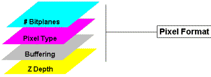
Figure 3. Pixel format properties
The primary property by which they are organized is the number of bits per pixel (BPP). Five bitplane organizations are supported, including 32 BPP, 24 BPP, 16 BPP, 8 BPP, and 4 BPP. Eight pixel formats are defined for the number of bits per pixel specified by the display driver. These are referred to as the native formats. The remaining 16 pixel formats (referred to as non-native formats) are divided evenly between the other bitplane organizations and are supplied for bitmap support. The formats are then organized by the pixel type (RGBA or color index), then buffering (single or double), and then the depth of the depth (z) buffer (32 or 16). Given this, you would think that there are 40 generic formats. However, 16 of the non-native formats are eliminated because it doesn’t make sense to double buffer to a bitmap. Table 1 lists all of the native formats.
Table 1. Native Pixel Formats
| Bits/Pixel | Pixel Type | Buffering | Depth (z) buffer |
| native | PFD_TYPE_RGBA | Single | 32 |
| native | PFD_TYPE_RGBA | Single | 16 |
| native | PFD_TYPE_RGBA | Double | 32 |
| native | PFD_TYPE_RGBA | Double | 16 |
| native | PFD_TYPE_COLORINDEX | Single | 32 |
| native | PFD_TYPE_COLORINDEX | Single | 16 |
| native | PFD_TYPE_COLORINDEX | Double | 32 |
| native | PFD_TYPE_COLORINDEX | Double | 16 |
Table 2 lists the remaining pixel formats. These are repeated for each non-native BPP format.
Table 2. Non-Native Pixel Formats
| Bits/Pixel | Pixel Type | Buffering | Depth (z) buffer |
| non-native | PFD_TYPE_RGBA | Single | 32 |
| non-native | PFD_TYPE_RGBA | Single | 16 |
| non-native | PFD_TYPE_COLORINDEX | Single | 32 |
| non-native | PFD_TYPE_COLORINDEX | Single | 16 |
Enumerating pixel formats is essential to finding a format that is appropriate for an application. Applications are responsible for defining "appropriate." MYGL looks for a native format. The formats are enumerated in response to one of two button clicks—one increases the pixel format index and the other decreases the index. The following code from PIXFORM.CPP demonstrates the enumeration technique used in MYGL. The m_nNextID member variable is used as an index of the pixel formats.
void CPixForm::OnClickedLastPfd()
{
  COpenGL gl;
  PIXELFORMATDESCRIPTOR pfd;
  //
  //Get the hwnd of the view window.
  //
  HWND hwndview = GetViewHwnd();
  //
  //Get a DC associated with the view window.
  //
  HDC   hdc   = ::GetDC(hwndview);
  int nID = (m_nNextID > 1) ?  m_nNextID-- : 1;
  //
  //Get a description of the pixel format. If it is valid, then go and
  //update the controls in the dialog box, otherwise do nothing.
  //
  if (gl.DescribePixelFormat(hdc, nID, sizeof(PIXELFORMATDESCRIPTOR), &pfd))
    UpdateDlg(&pfd);
  //
  //Release the DC.
  //
  ::ReleaseDC(hwndview, hdc);
}
Four functions, shown in Table 3, have been implemented to provide management of pixel formats.
Table 3. Pixel Format Functions
| Win32 Function | Description |
| ChoosePixelFormat | Obtains a device context's pixel format that is the closest match to a specified pixel format. |
| SetPixelFormat | Sets a window’s or bitmap’s current pixel format to the pixel format specified by a pixel format index. |
| GetPixelFormat | Obtains the pixel format index of a window’s or bitmap’s current pixel format. |
| DescribePixelFormat | Given a device context and a pixel format index, fills in a PIXELFORMATDESCRIPTOR data structure with the pixel format's properties. |
Figure 4 illustrates a general method for calling these functions.
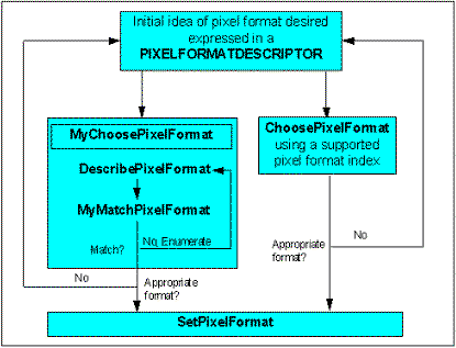
Figure 4. Calling pixel format functions
An application generally knows that it will be using double buffering, writing to the screen, or supporting GDI. This is the type of information that would be found in the top box of Figure 4 in PIXELFORMATDESCRIPTOR. The application can either call ChoosePixelFormat, which attempts to match the requested pixel format with the best supported (device or generic) pixel format available, or it can call its own pixel format matching function. The following list describes how ChoosePixelFormat attempts to match the requested pixel format to the pixel formats available:
PFD_DRAW_TO_WINDOW
PFD_DRAW_TO_BITMAP
PFD_SUPPORT_GDI
PFD_SUPPORT_OPENGL
PFD_TYPE_RGBA
PFD_TYPE_COLORINDEX
PFD_DOUBLEBUFFER
PFD_STEREO
cColorBits
cAlphaBits
cAccumBits
cDepthBits
cStencilBits
cAuxBuffers
iLayerType
Once you have an appropriate pixel format, SetPixelFormat is called. If SetPixelFormat is called for a device context that references a window, the function also changes the pixel format of the window. Changing the pixel format of a window more than once can lead to significant complications for the window manager and for multithreaded applications, so it is not allowed. An application can set the pixel format of a window only one time. Once a window's pixel format is set, it cannot be changed.
It is a simple matter to determine if a pixel format is a generic or device format. The following code illustrates the use of the dwFlags field of the PIXELFORMATDESCRIPTOR structure to detect if the pixel format is generic or device-specific.
BOOL COpenGL::IsDeviceIndex(HDC hdc, int idx)
{
  ASSERT (hdc);
  ASSERT (idx > 0);

  BOOL bRet = FALSE;
  PIXELFORMATDESCRIPTOR pfd;
  int ipfdmax = DescribePixelFormat(hdc, idx, sizeof(PIXELFORMATDESCRIPTOR),
                &pfd);

  if (!(pfd.dwFlags & PFD_GENERIC_FORMAT))
    bRet = TRUE;
  return (bRet);
}
If the PFD_GENERIC_FORMAT bit is set, the pixel format is generic (duh!). It is also very simple to detect if a given pixel format index is a native or non-native index. The following code illustrates this.
BOOL COpenGL::IsNativeIndex(HDC hdc, int idx)
{
  ASSERT (hdc);
  ASSERT (idx > 0);

  BOOL bRet = FALSE;
  PIXELFORMATDESCRIPTOR pfd;
  int ipfdmax = DescribePixelFormat(hdc, idx, sizeof(PIXELFORMATDESCRIPTOR),
                &pfd);

  if (pfd.dwFlags & PFD_DRAW_TO_WINDOW)
    bRet = TRUE;
  return (bRet);
}
If the PFD_DRAW_TO_WINDOW bit is set in dwFlags, the pixel format is native. This may include both generic and device-specific pixel formats. If this bit is not set, the pixel format is non-native and is provided for support of bitmaps.
As you begin to use device contexts with OpenGL/NT, remember two things:
To retrieve the index of the currently set pixel format, use the GetPixelFormat function. This function is used in several places in MYGL. The following code, found in COPENGL.CPP, illustrates its use.
int COpenGL::GetCurPFDIndex()
{
  int icuridx = GetPixelFormat(wglGetCurrentDC());
  return (icuridx);

}
In this code, GetPixelFormat is used to retrieve the pixel format index of the current DC. That index is then passed to DescribePixelFormat to obtain more information about the pixel format.
To retrieve the maximum number of device pixel formats supported for a given DC, use the DescribePixelFormat function. In the code below, the return value of DescribePixelFormat is assigned to the variable ipfdmax.
int COpenGL::GetMaxPFIndex(HDC hdc)
{
  PIXELFORMATDESCRIPTOR pfd;

  int ipfdmax = DescribePixelFormat(hdc, 1, sizeof(PIXELFORMATDESCRIPTOR),
                &pfd);

  return (ipfdmax);
}
The total number of device formats would be:
iDevMax = ipfdmax - 24
There are three important things to remember about rendering contexts:
An OpenGL/NT rendering context (GLRC) is composed of a handle to an OpenGL/NT driver (if any), a client handle (HGLRC), the current pixel format index, a thread ID, and a handle to the DC bound to the rendering context.
There are five functions, as shown in Table 4, that permit management of a rendering context.
Table 4. OpenGL/NT Rendering Context Functions (WGL Functions)
| WGL Function | Description |
| wglCreateContext | Creates a new rendering context. |
| wglMakeCurrent | Sets a thread's current rendering context. |
| wglGetCurrentContext | Obtains a handle to a thread's current rendering context. |
| wglGetCurrentDC | Obtains a handle to the device context that is associated with a thread's current rendering context. |
| wglDeleteContext | Deletes a rendering context. |
Of course all of these functions are important, but the one that will make or break you is wglMakeCurrent. It is the function that enables all drawing to take place on a DC. It makes the rendering context the calling thread’s current rendering context through which all OpenGL commands must "pass." Refer to the OpenGL/NT documentation for a more detailed description of these functions.
In general, an application calls wglCreateContext and then associates the context with a device surface by calling wglMakeCurrent. OpenGL drawing can then take place on the device surface, after which the rendering context can be unassociated with the DC by calling wglMakeCurrent again (with NULL arguments). Finally, the rendering context can be deleted by calling wglDeleteContext.
As you can see, device contexts (including pixel formats) and rendering contexts are closely associated. So, just how does it all fall together? It all starts with a device context.
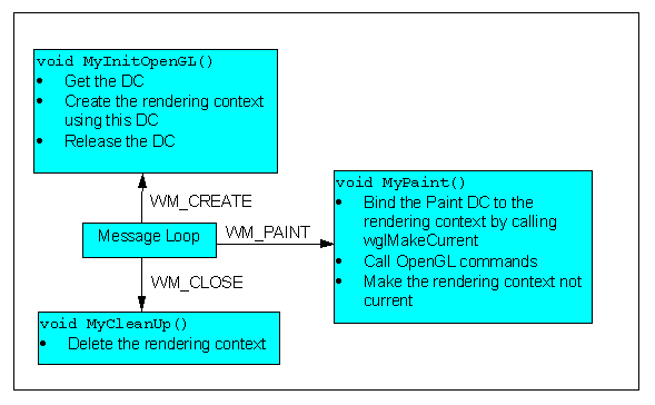
The DC is used to create an OpenGL rendering context. This context is used by OpenGL to draw to the DC and ultimately the device surface. There are two ways you can approach the use of DCs. In Figure 5, the DC is created during initialization and destroyed as the application closes. The fact that we are not pairing GetDC/CreateDC and ReleaseDC/DeleteDC within the same scope is unnerving to some. Ah yes, we have been conditioned! Arf arf...drool.
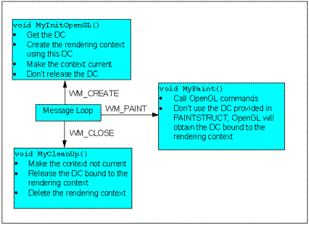
Figure 5. First approach to use of device contexts with OpenGL
Rest assured, you can follow your ingrained desire to delete the DC immediately after use. Figure 6 illustrates this. The rendering context is created in the response to WM_CREATE, and the DC used to create the context is released or deleted. It is not until the response to WM_PAINT that the rendering context is bound to a device context, in this case the Paint DC. It is important to note that this way of doing things is quite expensive. Making the context current is not trivial. The point to be made here is that a rendering context must be bound to a DC before OpenGL drawing can take place. You decide where and what DC you are going to bind to the rendering context (as long as the DC has the same pixel format as that used to create the rendering context).
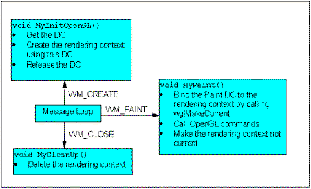
Figure 6. Second approach to use of device contexts with OpenGL
The OpenGL sample (GENGL) included with the Windows NT 3.5 Software Development Kit (SDK) takes the first approach. MYGL uses the first approach, although slightly modified. The rendering context is created in response to user input provided in a dialog box. When the dialog box is dismissed, the handle of the view window is used to obtain a DC and rendering context. When the view window is destroyed, the rendering context is deleted.
There is a little "gotcha" that can prevent setting the pixel format of a device context. The window in which OpenGL drawing will take place must have the style bits WS_CLIPCHILDREN and WS_CLIPSIBLINGS set. Otherwise, SetPixelFormat will fail. The following code taken from MYGLVIEW.CPP shows how to override the PreCreateWindow function in order to set these style bits.
BOOL CMyglView::PreCreateWindow(CREATESTRUCT& cs)
{
  //The view window style bits must include WS_CLIPSIBLINGS and
  //WS_CLIPCHILDREN so that the wgl functions will work.
  //
  cs.style = cs.style | WS_CLIPSIBLINGS | WS_CLIPCHILDREN;

  return CView::PreCreateWindow(cs);
}
After the user has entered preliminary PIXELFORMATDESCRIPTOR values by way of the Choose Pixel Format (CPIXFORM.CPP) dialog box, the OK button is clicked and the OnOK function is called. After validating the existence of a rendering context and the appropriateness of the pixel format, the following code, from MYGL (in COPENGL.CPP), is called to set up the pixel format and create the rendering context.
BOOL COpenGL::GetGLRC(HDC hdc)
{
   BOOL bRet = TRUE;

   ASSERT (m_pPixFmtDesc);

   if (SetupPixelFormat(hdc, m_pPixFmtDesc))
   {
     if ((m_hglrc = wglCreateContext(hdc)) != NULL)
     {
       if (!wglMakeCurrent(hdc, m_hglrc))
       {
         wglDeleteContext(m_hglrc);
         bRet = FALSE;
       }
     }
     else bRet = FALSE;
   }
   else
     bRet = FALSE;

   return bRet;
}
Once the pixel format is set up for the DC, the rendering context is created by a call to wglCreateContext. If the rendering context was successfully created, it is bound to the current DC. Note that this DC is not released. This does not happen until MYGL closes.
MYGL draws by issuing OpenGL commands in the OnDraw function found in MYGLVIEW.CPP.
void CMyglView::OnDraw(CDC* pDC)
{
  CMyglDoc* pDoc = GetDocument();
  RECT rc;
  COpenGL gl;
  HGLRC hglrc = gl.wglGetCurrentContext();

  if (hglrc)
  {
    GetClientRect(&rc);
    DrawScene(rc);
  }

}
The wglGetCurrentContext function is called to ensure that there is in fact a rendering context. However, if there was not, nothing adverse would happen. No drawing would take place. Note that the DC associated with pDC is not passed to DrawScene. The DC is implicit and is the DC associated with the rendering context.
The following code is called when MYGL closes.
BOOL COpenGL::ReleaseGLRC(HWND hwnd)
{
  BOOL bRet = TRUE;
  HDC   hdc;
  HGLRC hglrc;

  if (hglrc = wglGetCurrentContext())
  {
    //
    //Get the DC associated with the rendering context.
    //
    hdc = wglGetCurrentDC();
    //
    //Make the rendering context not current.
    //
    wglMakeCurrent(NULL, NULL);
    //
    //Nuke the DC.
    //
    ::ReleaseDC(hwnd, hdc);
   //
   //Nuke the rendering context.
   //
   wglDeleteContext(hglrc);
  }
  else bRet = FALSE;
  return bRet;

}
After retrieving the current DC, using wglGetCurrentDC, it is released. The rendering context is then released.
Windows NT version 3.5 provides OpenGL capabilities. In the generic implementation, all of the pixel format and rendering management is handled by GDI. In the device implementation, much of this management is supported by the device. Before OpenGL drawing can take place, the window, bitmap, or device’s pixel format must be set up. A rendering context is then created. At this point, drawing can take place. Now that Windows NT provides the structure and functions for 3-D graphics, it is up to applications developers to provide the cool applications. Have fun.
Future technical articles will zero in on OpenGL specifics. Stay tuned.
OpenGL Reference Manual, The Official Reference Document for OpenGL, Release 1. OpenGL Architecture Review Board, 1992, Addison Wesley, ISBN 0-201-63276-4.
OpenGL Programming Guide, The Official Guide to Learning OpenGL, Release 1. OpenGL Architecture Review Board, 1992, Addison Wesley, ISBN 0-201-63274-8.
Windows NT SDK, Windows NT OpenGL documentation (pre-release)