Microsoft Corporation
Updated April 1999
Summary: Telephony Application Program Interface (TAPI) 3.0 is an evolutionary API providing convergence of both traditional PSTN telephony and IP telephony. IP telephony is an emerging set of technologies that enables voice, data, and video collaboration over existing LANs, WANs, and the Internet. TAPI 3.0 enables IP telephony on Microsoft® Windows® operating systems by providing simple and generic methods for making connections between two or more computers and accessing any media streams involved in the connection.
TAPI 3.0 supports standards-based H.323 conferencing and IP multicast conferencing. It uses the Microsoft Windows 2000 operating system's Active Directory™ service to simplify deployment within an organization and includes quality-of-service (QoS) support to improve conference quality and network manageability. (33 printed pages)
IP Telephony
Introduction to TAPI 3.0
H.323 Communications in TAPI 3.0
IP Multicast Conferencing in TAPI 3.0
Quality of Service
Enterprise Deployment of TAPI 3.0 IP Telephony Infrastructure
TAPI 3.0 and NetMeeting 2.0
IP telephony is an emerging set of technologies that enables voice, data, and video collaboration over existing IP-based LANs, WANs, and the Internet.
Specifically, IP telephony uses open IETF and ITU standards to move multimedia traffic over any network that uses IP, offering users both flexibility in physical media (for example, POTS lines, ADSL, ISDN, leased lines, coaxial cable, satellite, and twisted pair) and flexibility of physical location. As a result, the same ubiquitous networks that carry Web, e-mail, and data traffic can be used to connect to individuals, businesses, schools, and governments worldwide.
TAPI 3.0 is an evolutionary API that supports convergence of both traditional PSTN telephony and telephony over IP networks.
IP telephony allows organizations and individuals to lower the costs of existing services, such as voice and broadcast video, while broadening their means of communication to include modern video conferencing, application sharing, and whiteboarding tools.
In the past, organizations have deployed separate networks to handle traditional voice, data, and video traffic. Each with different transport requirements, these networks were expensive to install, maintain, and reconfigure. Furthermore, since these networks were physically distinct, integration was difficult, if not impossible, limiting their potential usefulness.
IP telephony blends voice, video, and data by specifying a common transport, IP, for each, effectively collapsing three networks into one. The result is increased manageability, lower support costs, a new breed of collaboration tools, and increased productivity.
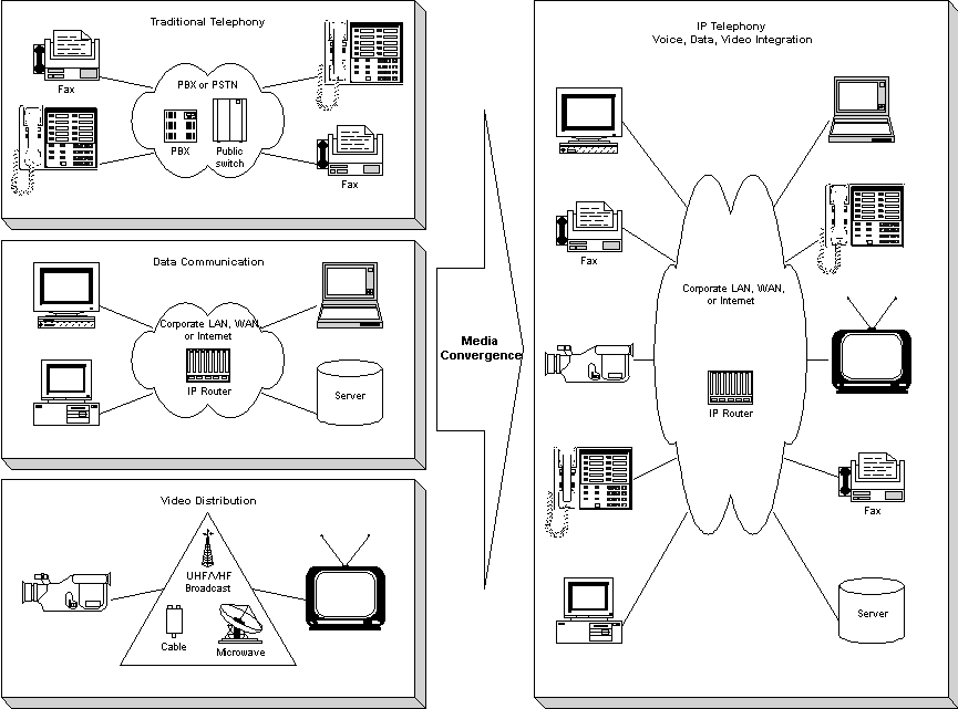
Possible applications for IP telephony include telecommuting, real-time document collaboration, distance learning, employee training, video conferencing, video mail, and video on demand. See Figure 1.

Figure 1. Media Convergence: voice, data, and video
As telephony and call control become more common in the desktop computer, a general telephony interface is needed to enable applications to access all the telephony options available on any computer. The media or data on a call must also be available to applications in a standard manner.
TAPI 3.0 provides simple and generic methods for making connections between two or more computers and accessing any media streams involved in that connection. It abstracts call-control functionality to allow different, and seemingly incompatible, communication protocols to expose a common interface to applications.
IP telephony is poised for explosive growth, as organizations begin a historic shift from expensive and inflexible circuit-switched public telephone networks to intelligent, flexible, and inexpensive IP networks. Microsoft, in anticipation of this trend, has created a robust computer telephony infrastructure, TAPI. Now in its third major version, TAPI is suitable for quick and easy development of IP telephony applications. See Figure 2.
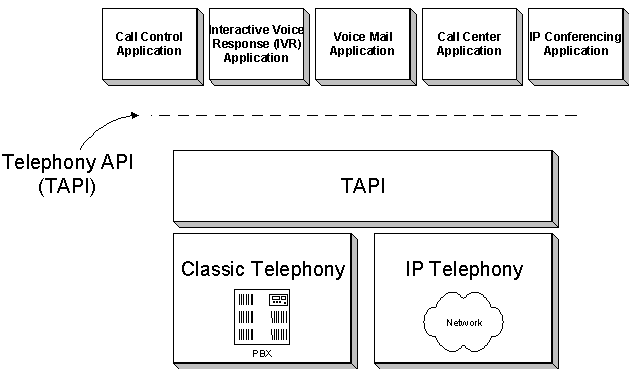
Figure 2. Convergence of IP and PSTN telephony
TAPI 3.0 integrates multimedia stream control with legacy telephony. Additionally, it is an evolution of the TAPI 2.1 API to the COM model, allowing TAPI applications to be written in any language, such as C/C++ or Microsoft® Visual Basic®.
Besides supporting classic telephony providers, TAPI 3.0 supports standard H.323 conferencing and IP multicast conferencing. TAPI 3.0 uses the Windows 2000 Active Directory service to simplify deployment within an organization, and it supports quality-of-service (QoS) features to improve conference quality and network manageability. See TAPI architecture in Figure 3.
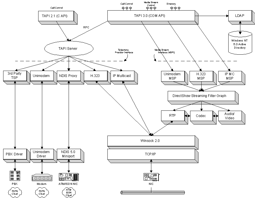
Figure 3. TAPI architecture
There are four major components to TAPI 3.0:
In contrast to TAPI 2.1, the TAPI 3.0 API is implemented as a suite of COM objects. Moving TAPI to the COM model allows component upgrades of TAPI features. It also allows developers to write TAPI-enabled applications in any language.
The TAPI Server process (TAPISRV.EXE) abstracts the TSPI (TAPI Service Provider Interface) from TAPI 3.0 and TAPI 2.1, allowing TAPI 2.1 Telephony Service Providers to be used with TAPI 3.0, maintaining the internal state of TAPI.
Telephony Service Providers (TSPs) are responsible for resolving the protocol-independent call model of TAPI into protocol-specific call-control mechanisms. TAPI 3.0 provides backward compatibility with TAPI 2.1 TSPs. Two IP telephony service providers (and their associated MSPs) ship by default with TAPI 3.0: the H.323 TSP and the IP Multicast Conferencing TSP, which are discussed below.
TAPI 3.0 provides a uniform way to access the media streams in a call, supporting the DirectShowTM API as the primary media-stream handler. TAPI Media Stream Providers (MSPs) implement DirectShow interfaces for a particular TSP and are required for any telephony service that makes use of DirectShow streaming. Generic streams are handled by the application.
There are five objects in the TAPI 3.0 API, as illustrated in Figure 4:
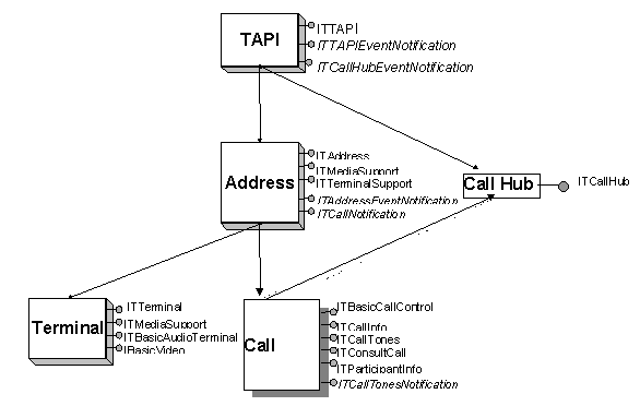
Figure 4. TAPI 3.0 object relationships
The TAPI object is the application's entry point to TAPI 3.0. This object represents all telephony resources to which the local computer has access, allowing an application to enumerate all local and remote addresses.
An Address object represents the origination or destination point for a call. Address capabilities, such as media and terminal support, can be retrieved from this object. An application can wait for a call on an Address object or can create an outgoing call object from an Address object.
A Terminal object represents the sink, or renderer, at the termination or origination point of a connection. The Terminal object can map to hardware used for human interaction, such as a telephone or microphone, but can also be a file or any other device capable of receiving input or creating output.
The Call object represents an address's connection between the local address and one or more other addresses (This connection can be made directly or through a CallHub). The Call object can be imagined as a first-party view of a telephone call. All call control is done through the Call object. There is a Call object for each member of a CallHub.
The CallHub object represents a set of related calls. A CallHub object cannot be created directly by an application—it is created indirectly when an incoming call is received through TAPI 3.0. Using a CallHub object, a user can enumerate the other participants in a call or conference, and possibly (because of the location independent nature of COM) perform call control on the remote Call objects associated with those users, subject to sufficient permissions. See Figure 5.
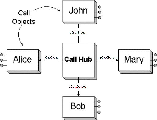
Figure 5. Call and CallHub object relationships
The Windows® operating system provides an extensible framework for efficient control and manipulation of streaming media called DirectShow. DirectShow, through its exposed COM interfaces, provides TAPI 3.0 with unified stream control.
At the heart of DirectShow is a modular system of pluggable components called filters, arranged in a configuration called a filter graph. A component called the filter graph manager oversees the connection of these filters and controls the stream's data flow. Each filter's capabilities are described by a number of special COM interfaces called pins. Each pin instance can consume or produce streaming data, such as digital audio.
While COM objects are usually exposed in user-mode programs, the DirectShow streaming architecture includes an extension to the Windows driver model that allows the connection of media streams directly at the device-driver level. Figure 6 below shows a simple PSTN-to-IP bridge: A 64 Kbps voice stream from an ISDN line is compressed into a G.723 audio stream and passed to an RTP payload handler to be sent out over the network.

Figure 6. Sample DirectShow filter graph with user and kernel-mode components
These high-performance streaming extensions to the Windows Driver Model avoid user-to-kernel mode transitions and allow efficient routing of data streams between different hardware components at the device driver level. Each kernel mode filter is mirrored by a corresponding user-mode proxy that facilitates connection setup and can be used to control hardware-specific features.
DirectShow network filters extend the streaming architecture to computers connected on an IP network. The Real-time Transport Protocol (RTP), designed to carry real-time data over connectionless networks, transports TAPI media streams and provides appropriate time-stamp information. TAPI 3.0 includes a kernel-mode RTP network filter.
TAPI 3.0 utilizes this technology to present a unified access method for the media streams in multimedia calls. Applications can route these streams by manipulating corresponding filter graphs; they can also easily connect streams from multiple calls for bridging and conferencing capabilities.
H.323 is a comprehensive International Telecommunications Union (ITU) standard for multimedia communications (voice, video, and data) over connectionless networks that do not provide a guaranteed quality of service, such as IP-based networks and the Internet. It provides for call control, multimedia management, and bandwidth management for point-to-point and multipoint conferences. H.323 mandates support for standard audio and video codecs and supports data sharing through the T.120 standard. Furthermore, the H.323 standard is network-, platform-, and application-independent, allowing any H.323-compliant terminal to interoperate with any other. See Figure 7.
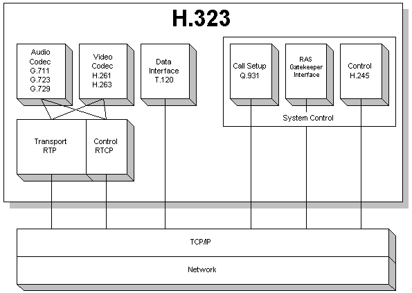
Figure 7. H.323 architecture
H.323 allows multimedia streaming over current packet-switched networks. To counter the effects of LAN latency, H.323 uses as a transport the Real-time Transport Protocol (RTP), an IETF standard designed to handle the requirements of streaming real-time audio and video over the Internet.
The H.323 standard specifies three command and control protocols:
The H.245 control channel is responsible for control messages governing operation of the H.323 terminal, including capability exchanges, commands, and indications. Q.931 is used to set up a connection between two terminals, while RAS governs registration, admission, and bandwidth functions between endpoints and gatekeepers (RAS is not used if a gatekeeper is not present). See below for more information on gatekeepers.
H.323 defines four major components of an H.323-based communication system:
Terminals are the client endpoints on the network. All terminals must support voice communications; video and data support is optional.
A Gateway is an optional element in an H.323 conference. Gateways bridge H.323 conferences to other networks, communications protocols, and multimedia formats. Gateways are not required if connections to other networks or non-H.323-compliant terminals are not needed.
Gatekeepers perform two important functions that help maintain the robustness of the network: address translation and bandwidth management. Gatekeepers map LAN aliases to IP addresses and provide address lookups when needed. Gatekeepers also exercise call-control functions to limit the number of H.323 connections and the total bandwidth used by these connections, in an H.323 zone. A gatekeeper is not required in an H.323 system; however, if a gatekeeper is present, terminals must make use of its services. See Figure 8.
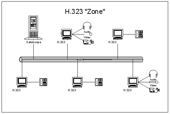
Figure 8. H.323 components
Multipoint Control Units (MCU) support conferences between three or more endpoints. An MCU consists of a required Multipoint Controller (MC) and 0 or more Multipoint Processors (MPs). The MC performs H.245 negotiations between all terminals to determine common audio and video processing capabilities, while the Multipoint Processor (MP) routes audio, video, and data streams between terminal endpoints.
Any H.323 client is guaranteed to support the following standards: H.261 and G.711. H.261 is an ITU-standard video codec designed to transmit compressed video at a rate of 64 Kbps and at a resolution of 176x44 pixels (QCIF). G.711 is an ITU-standard audio codec designed to transmit A-law and µ-law PCM audio at bit rates of 48, 56, and 64 Kbps.
Optionally, an H.323 client may support additional codecs: H.263 and G.723. H.263 is an ITU-standard video codec based on and compatible with H.261. It offers improved compression over H.261 and transmits video at a resolution of 176 x 44 pixels (QCIF). G.723 is an ITU-standard audio codec designed to operate at very low bit rates.
The H.323 Telephony Service Provider (with its associated Media Stream Provider) allows TAPI-enabled applications to engage in multimedia sessions with any H.323-compliant terminal on the local area network.
Specifically, the H.323 Telephony Service Provider (TSP) implements the H.323 signaling stack. The TSP accepts a number of different address formats, including name, computer name, and e-mail address.
The H.323 MSP is responsible for constructing the DirectShow filter graph for an H.323 connection (including the RTP, RTP payload handler, codec, sink, and renderer filters). See diagram of the H.323 architecture in Figure 9.
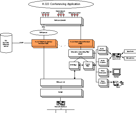
Figure 9. H.323 TSP architecture
H.323 telephony is complicated by the fact that a user's network address (in this case, a user's IP address) is highly volatile and cannot be counted on to remain unchanged between H.323 sessions. The TAPI H.323 TSP uses the services of the Windows 2000 Active Directory to perform user-to-IP address resolution. Specifically, user-to-IP mapping information is stored and continually refreshed using the Internet Locator Service (ILS) Dynamic Directory, a real-time server component of the Active Directory.
The following user scenario illustrates IP address resolution in the H.323 TSP:
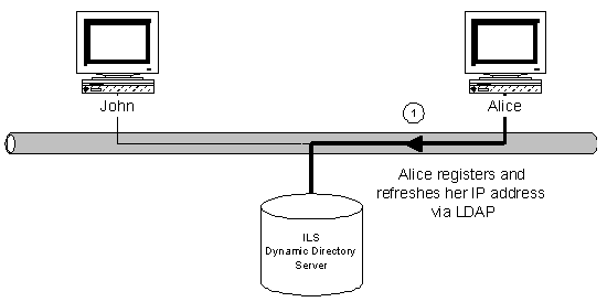
Figure 10. Alice registers and refreshes her IP address
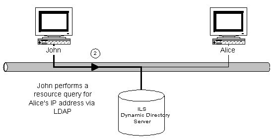
Figure 11. John queries for Alice's IP address
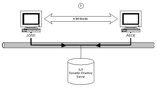
Figure 12. Once capability negotiations have been completed, the conference begins
IP multicast is an extension of IP that allows for efficient group communication. IP multicast arose out of the need for a lightweight, scalable conferencing solution that solved the problems associated with real-time traffic over a datagram, best-effort network. There are many advantages to using IP multicast: scalability, fault tolerance, robustness, and ease of setup.
The IP multicast conferencing model incorporates the following key features:
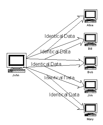
Figure 13. Network topology: sender's view
The total bandwidth required for multiparty conferences in which all users are sending data goes up as the square of the number of parties involved, leading to huge scalability problems. IP Multicast takes advantage of the actual network topology to eliminate the transmission of redundant data down the same communications links. See Figure 14.
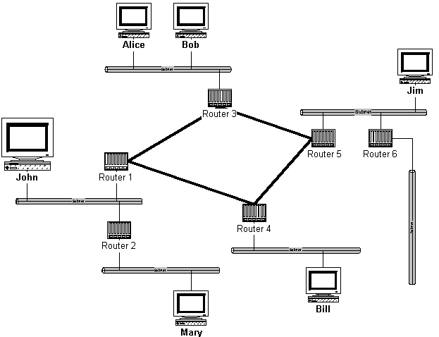
Figure 14. Actual network topology
IP multicast implements a lightweight, session-based communications model, which places relatively little burden on conference users. Using IP multicast, users send only one copy of their information to a group IP address that reaches all recipients. IP multicast is designed to scale well as the number of participants expands—adding one more user does not add a corresponding amount of bandwidth. Multicasting also results in a greatly reduced load on the sending server.
IP multicast routes these one-to-many data streams efficiently by constructing a spanning tree, in which there is only one path from one router to any other. Copies of the stream are made only when paths diverge. See Figure 15.
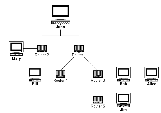
Figure 15. IP multicast using a spanning tree
Without multicasting, the same information must either be carried over the network multiple times, one time for each recipient, or broadcast to everyone on the network, consuming unnecessary bandwidth and processing.
IP multicast uses Class-D Internet Protocol addresses to specify multicast host groups, ranging from 224.0.0.0 to 239.255.255.255. Both permanent and temporary group addresses are supported. Permanent addresses are assigned by the Internet Assigned Numbers Authority (IANA) and include 224.0.0.1, the all-hosts group used to address all multicast hosts on the local network, and 224.0.0.2, which addresses all routers on a LAN. The range of addresses between 224.0.0.0 and 224.0.0.255 is reserved for routing and other low-level network protocols. Other addresses and ranges have been reserved for applications, such as 224.0.13.000 to 224.0.13.255 for Net News (for more information, see RFC 1700, "Assigned Numbers" at ftp://ftp.internic.net/rfc/rfc1700.txt).
The transport protocol for IP Multicast is RTP (Real-time Transport Protocol), which provides a standard multimedia header giving time stamp, sequence numbering, and payload format information.
Applications for IP multicast include video and audio conferencing, telecommuting, database and Web-site replication, distance learning, dissemination of stock quotes, and collaborative computing. At present, the largest demonstration of the capabilities of IP multicast is the Internet MBONE (Multicast Backbone).
The MBONE is an experimental, global multicast network layered on top of the physical Internet. It has been in existence for about five years, and presently carries IETF meetings, NASA space shuttle launches, music, concerts, and many other live meetings and performances (for more information, see http://www.mbone.com).
The IP Multicast Conferencing TSP is chiefly responsible for resolving conference names to IP multicast addresses, using the Session Description Protocol (SDP) conference descriptors stored in the ILS Dynamic Directory Conference Server. It is complemented by the Rendezvous conference controls, described below.
The IP Multicast Conferencing MSP is responsible for constructing an appropriate DirectShow filter graph for an IP multicast connection (including RTP, RTP payload handler, codec, sink, and renderer filters). See IP multicast conference architecture in Figure 16.
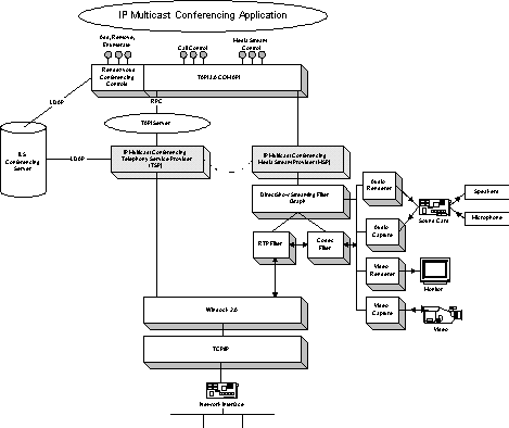
Figure 16. IP multicast conferencing architecture
TAPI 3.0 uses the IETF-standard Session Description Protocol to advertise IP multicast conferences across the enterprise. SDP descriptors are stored in the Windows 2000 Active Directory—specifically, in the ILS Dynamic Directory Conference Server. SDP is discussed in more detail below. In contrast to the Dynamic Directory servers utilized by the H.323 TSP, there is only one ILS Conference Server per enterprise, since conference announcements are not continually refreshed, therefore consuming little bandwidth.
TAPI 3.0's IP multicast conference mechanism is illustrated in the following scenario, in which John wishes to initiate a multicast conference:
John's TAPI 3.0-enabled application uses the Rendezvous Controls (discussed in more detail below) to create an SDP session descriptor on the ILS Conference Server. The SDP descriptor contains, among other things, the conference name, start and end times, the IP multicast address of the conference, and the media types used for the conference. See Figure 17.
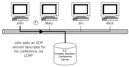
Figure 17. John adds an SDP session descriptor
Jim queries the ILS Conference Server for SDP descriptors of conferences matching his criteria. See Figure 18.
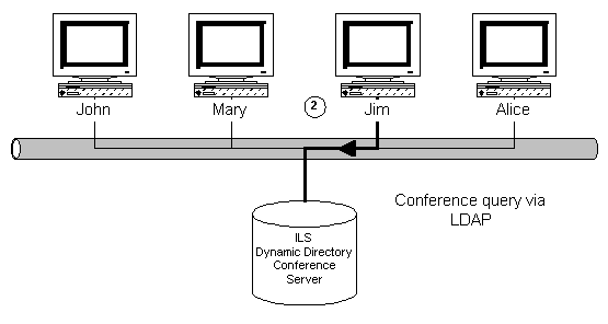
Figure 18. Jim queries the ILS Conference Server
Mary and Alice perform similar queries and use the SDP information they receive to decide to participate in John's conference. With the multicast IP address of the conference, they join the multicast host group. See Figure 19.
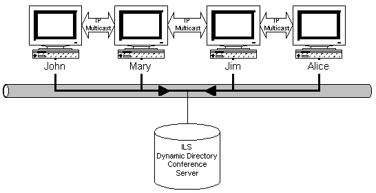
Figure 19. Mary and Alice join the conference
The Rendezvous Controls are a set of COM components that abstract the concept of a conference directory, providing a mechanism to advertise new multicast conferences and to discover existing ones. They provide a common schema (SDP) for conference announcement, as well as scriptable interfaces, authentication, encryption, and access-control features. See Figure 20.
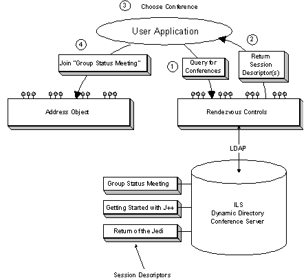
Figure 20. Joining a conference, using the Rendezvous controls
The user may add, delete, and enumerate multicast conferences stored on an ILS Conference Server through the Rendezvous controls. These controls manipulate conference data through the Lightweight Directory Access Protocol (LDAP).
Joining a conference is illustrated in Figure 20 above. The conferencing application uses the Rendezvous controls to obtain session descriptors for the conferences that match the user's criteria (1,2). Access control lists (ACLs) protect each of the stored conference announcements, and whether or not an announcement is visible and accessible depends upon the user's credentials.
Once the user has chosen a conference (3), the user application searches for all Address objects that support the address type Multicast Conference Name. The application then uses the conference name from the SDP descriptor as a parameter to the CreateCall method of the appropriate Address object (4), passes the appropriate Terminal objects to the returned Call object, and calls Call->Connect.
The Rendezvous controls store the conference information on an ILS Conference Server in a format defined by the Session Description Protocol (SDP), an IETF standard for announcing multimedia conferences. The purpose of SDP is to publicize sufficient information about a conference (time, media, and location information) to allow prospective users to participate if they choose. Originally designed to operate over the Internet MBONE (IP Multicast Backbone), SDP has been integrated by TAPI 3.0 with the Windows 2000 Active Directory, thus extending its functionality to local area networks.
An SDP descriptor advertises the following information in Figure 21 about a conference:
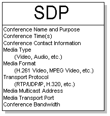
Figure 21. General SDP attributes
A session description is broken into three main parts: a single Session Description, 0 or more Time Descriptions, and 0 or more Media Descriptions. The Session Description contains global attributes that apply to the whole conference or all media streams. Time Descriptions contain conference start, stop, and repeat-time information, and Media Descriptions contain details that are specific to a particular media stream.
While traditional IP multicast conferences operating over the MBONE have advertised conferences using a push model based on the Session Announcement Protocol (SAP), TAPI 3.0 employs a pull-based approach, using Windows 2000 Active Directory services. This approach offers numerous advantages, among them bandwidth conservation and ease of administration. See the Integration with Windows 2000 Active Directory section for details.
TAPI 3.0's conference security system addresses the following needs:
TAPI 3.0 uses the security features of the Windows 2000 Active Directory and LDAP to provide for secure conferencing over insecure networks, such as the Internet. Each object in the Active Directory can be associated with an Access Control List (ACL) specifying object-access rights on a user or group basis. By associating ACLs with SDP conference descriptors, conference creators can specify who can enumerate and view conference announcements. User authentication is provided by the Windows 2000 security subsystem. See Figure 22.
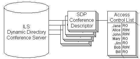
Figure 22. SDPs and ACLs
Session Descriptors are transmitted from the ILS Conference Server to the user over LDAP in encrypted form, through a Secure Sockets Layer (SSL) connection, ensuring that the SDP is safe from eavesdroppers. See Figure 23.
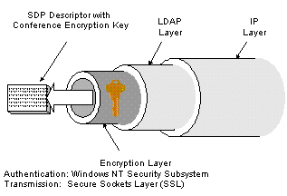
Figure 23. Distribution of the SDP
IP multicast makes no provision for authenticating users; any user may anonymously join a multicast host group. To keep conferences private, TAPI 3.0 allows an IP multicast conference to be encrypted, with the encryption key distributed from within the conference descriptor. Only users with sufficient permissions have access to a conference's SDP descriptor and, therefore, the multicast encryption key. Once an authenticated user fetches the encryption key, he or she can participate in the conference. See Figure 24.
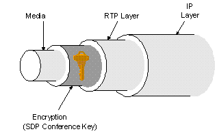
Figure 24. Encrypted multicast stream
In contrast to traditional data traffic, multimedia streams, such as those used in IP telephony or videoconferencing, may be extremely bandwidth- and delay-sensitive, imposing unique quality-of-service (QoS) demands on the underlying networks that carry them. Unfortunately, IP, with a connectionless, best-effort delivery model, does not guarantee delivery of packets in order, in a timely manner, or at all. In order to deploy real-time applications over IP networks with an acceptable level of quality, certain bandwidth, latency, and jitter requirements must be guaranteed and met so that multimedia traffic can coexist with traditional data traffic on the same network.
Bandwidth: Multimedia data, and in particular video, requires orders of magnitude more bandwidth than traditional networks can handle. An uncompressed NTSC video stream, for example, can require upwards of 220 megabits per second. Even compressed, a handful of multimedia streams can completely overwhelm any other traffic on the network.
Latency: The amount of time that a multimedia packet takes to get from the source to the destination (latency) has a major impact on the perceived quality of the call. There are many contributors towards latency, including transmission delays, queuing delays in network equipment, and delays in host protocol stacks. Latency must be minimized in order to maintain a certain level of interactivity and to avoid unnatural pauses in conversation.
Jitter: In contrast to data traffic, real-time multimedia packets must arrive in order and on time to be of any use to the receiver. Variations in packet arrival time (jitter) must be below a certain threshold to avoid dropped packets (and therefore irritating shrieks and gaps in the call). Jitter, by determining receive buffer sizes, also affects latency.
Coexistence: In comparison with multimedia traffic, data traffic is relatively bursty, and arrives in unpredictable chunks (for instance, when someone opens a Web page, or downloads a file from an FTP site). Aggregations of such bursts can clog routers and cause gaps in multimedia conferences, leaving calls at the mercy of everyone on the network (including other IP telephony users). Multimedia bandwidth must be protected from data traffic, and vice versa.
Public-switched telephone networks guarantee a minimum quality of service by allocating static circuits for every telephone call. Such an approach is simple to implement, but wastes bandwidth, lacks robustness, and makes voice, video, and data integration difficult. Furthermore, circuit-switched data paths are impossible to create using a connectionless network such as IP.
QoS support on IP networks offers the following benefits:
Quality of service in TAPI 3.0 is handled through the DirectShow RTP filter, which negotiates bandwidth capabilities with the network, based on the requirements of the DirectShow codecs associated with a particular media stream. These requirements are indicated to the RTP filter by the codecs through its own QoS interface. The RTP filter then uses the COM Winsock2 GQoS interfaces to indicate, in an abstract form, its QoS requirements to the Winsock2 QoS service provider (QoS SP). The QoS SP, in turn, invokes various QoS mechanisms appropriate for the application, the underlying media, and the network, in order to guarantee appropriate end-to-end QoS. These mechanisms include:
The Resource Reservation Protocol (RSVP) is an IETF standard designed to support resource (for example, bandwidth) reservations through networks of varying topologies and media. Through RSVP, a user's QoS requests are propagated to all routers along the data path, allowing the network to reconfigure itself (at all network levels) to meet the desired level of service.
The RSVP protocol engages network resources by establishing flows throughout the network. A flow is a network path associated with one or more senders, one or more receivers, and a certain QoS. A sending host wishing to send data that requires a certain QoS broadcasts, through an RSVP-enabled Winsock Service Provider, path messages toward the intended recipients. These path messages, which describe the bandwidth requirements and relevant parameters of the data to be sent, are propagated to all intermediate routers along the path.
A receiving host, interested in this particular data, confirms the flow (and the network path) by sending reserve messages through the network, describing the bandwidth characteristics of data it should receive from the sender. As these reserve messages propagate back toward the sender, intermediate routers, based on bandwidth capacity, decide whether or not to accept the proposed reservation and commit resources. If an affirmative decision is made, the resources are committed and reserve messages are propagated to the next hop on the path from source to destination. See Figure 25.
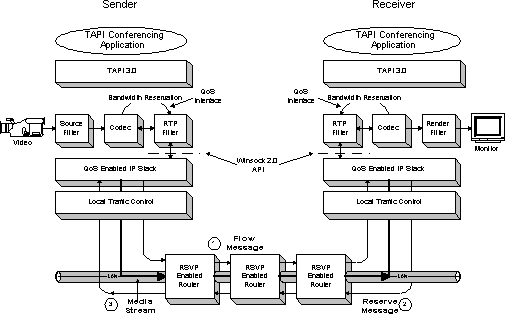
Figure 25. Resource reservation with TAPI 3.0
Packet Scheduling: This mechanism can be used in conjunction with RSVP (if the underlying network is RSVP-enabled) or without RSVP. Traffic is identified as belonging to one flow or another, and packets from each flow are scheduled in accordance with the traffic-control parameters for the flow. These parameters generally include a scheduled rate (token bucket parameter) and some indication of priority. The former is used to pace the transmission of packets to the network. The latter is used to determine the order in which packets should be submitted to the network when congestion occurs.
801.2p: Traffic control can also be used to determine the 802.1 User Priority value (a MAC header field used to indicate relative packet priority) to be associated with each transmitted packet. 802.1p-enabled switches can then give preferential treatment to certain packets over others, providing additional QoS support at the data-link-layer level.
Layer 2 Signaling Mechanisms: In response to Winsock 2 QoS APIs, the QoS service provider may invoke additional traffic-control mechanisms, depending on the specific underlying data-link layer. It may signal an underlying ATM network, for instance, to set up an appropriate virtual circuit for each flow. When the underlying medium is a traditional 802 shared media network, the QoS service provider may extend the standard RSVP mechanism to signal a Subnet Bandwidth Manager (SBM). The SBM provides centralized bandwidth management on shared networks.
Each IP packet contains a three-bit Precedence field, which indicates the priority of the packet. An additional field can be used to indicate a delay, throughput, or reliability preference to the network. Local traffic control can be used to set these bits in the IP headers of packets on particular flows. As a result, packets belonging to a flow are treated appropriately later by three devices on the network. These fields are analogous to 802.1p priority settings but are interpreted by higher-layer network devices.
TAPI 3.0 has been designed to scale from the smallest business up to the largest organizations, while taking advantage of the Windows 2000 Active Directory to bring IP telephony to the enterprise.
Figure 26 below illustrates the enterprise layout for a sample enterprise with two sites connected through the Internet. The ILS Dynamic Directory Servers and the ILS Dynamic Directory Conference Server, as explained above, provide functionality for point-to-point and multiparty conferencing. IP telephony clients can use video and audio capture equipment and can also support legacy telephones through the use of a PSTN add-in card.
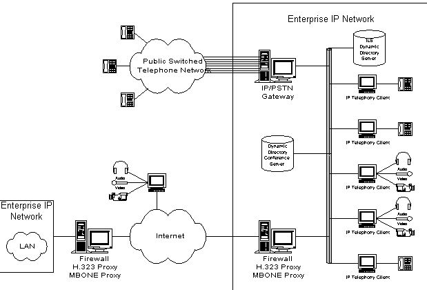
Figure 26. Enterprise layout for IP telephony
The IP/PSTN gateway digitizes incoming analog voice calls from PSTN lines and encapsulates them in H.323 streams, and vice versa, providing users with the ability to send and receive legacy voice calls through existing telephony infrastructure.
The H.323 Proxy allows H.323 clients to have connectivity with the Internet by forwarding H.323 streams through the enterprise firewall. This enables H.323 Internet, intranet, and business-to-business connectivity.
The function of the IP Multicast Proxy is somewhat similar to that of the H.323 Proxy—to forward multicast conference packets, but it also furnishes clients with the ability to propagate selected conference announcements to and from the Internet.
The IP Multicast Proxy monitors conference announcements stored on the ILS Dynamic Directory Conference Server and broadcasts conferences with appropriate scope and security attributes to the Internet, using the Session Announcement Protocol (SAP).
Conversely, the IP Multicast Proxy listens for appropriate conferences from those broadcast over the Internet and populates the ILS Dynamic Directory Conference Server with these announcements. In this manner, the IP Multicast Proxy allows users conference connectivity over the Internet while ensuring the confidentiality and security of private conferences.
As discussed earlier, the H.323 TSP uses the services of the ILS Dynamic Directory component of the Active Directory to remove the burden of name-to-IP translation from the user.
At the network level, the Windows 2000 Active Directory model treats an organization as a collection of sites. Sites are regions of good connectivity, such as subnets or LANs, and typically correlate with physical locales, such as campuses.
For bandwidth and performance reasons, ILS servers are typically distributed across the enterprise, one per site, with each ILS server (or a replicating cluster of severs) being responsible for maintaining user-to-IP mappings for their site. To conserve bandwidth, these volatile mappings are not replicated across sites.
TAPI 3.0 uses the Active Directory to associate users with particular ILS servers. Users wishing to place an IP telephone call first consult the Global Catalog (a replicated subset of the Active Directory) for the User object of the person they wish to call. The Telephony container in the User object contains the name of the ILS server for that user's site, which is then queried for the IP address in question. See Figure 27.
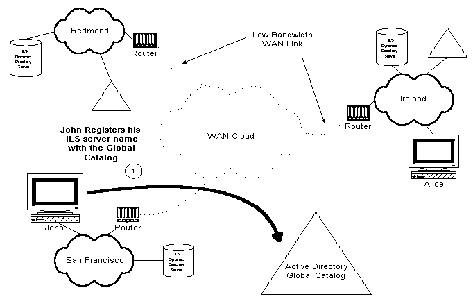
Figure 27. IP telephone call process
The following scenario illustrates enterprise deployment of the TAPI 3.0 directory infrastructure. In this example, Alice wants to initiate an H.323 call to John.
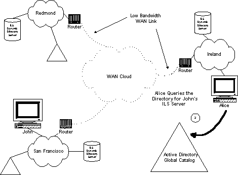
Figure 28. Alice's TSP queries her local copy of the Global catalog.
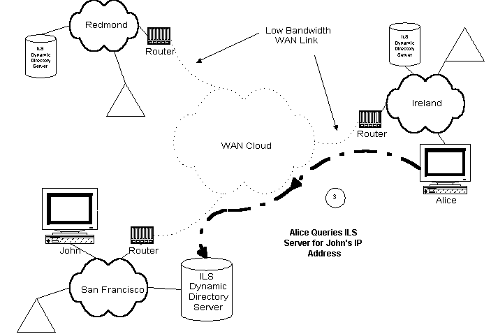
Figure 29. Alice's TSP queries for John's IP address.
Alice then initiates an H.323 session with John, as shown in Figure 30.
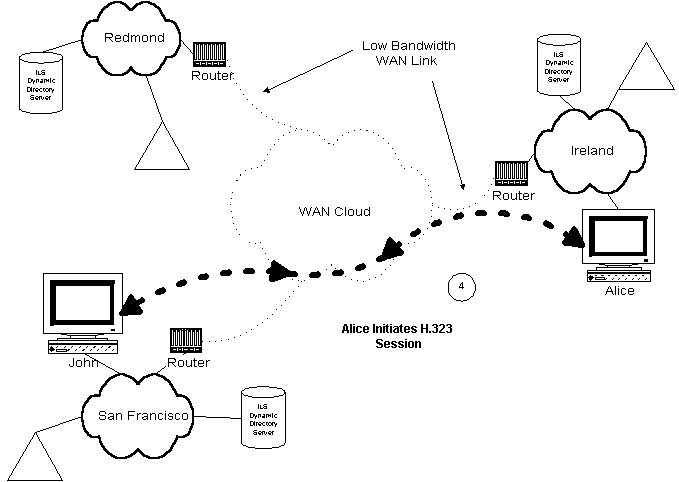
Figure 30. Alice initiates a session with John.
The call abstraction inherent in TAPI allows this ILS and Active Directory interaction to occur transparently both to the user and to the TAPI 3.0-enabled application.
Microsoft NetMeeting is a conferencing and collaboration tool designed for the Internet or intranet. NetMeeting also provides a set of programming interfaces for adding conferencing functionality to your applications. It helps small and large organizations take full advantage of the global reach of the Internet or corporate intranet for real-time communications and collaboration by combining IP telephony and conferencing functionality. Connecting to other NetMeeting users is made easy with the Microsoft Internet Locator Server (ILS), enabling participants to call each other from a dynamic directory within NetMeeting or from a Web page. While connected on the Internet or corporate intranet, participants can communicate with both voice and video, work together on virtually any Windows-based application, exchange or mark up graphics on an electronic whiteboard, transfer files, or use the text-based chat program. For more information on Microsoft NetMeeting 2.0, see www.microsoft.com/windows/netmeeting/default.asp.
Microsoft NetMeeting 2.0 has the following features:
H.323 standards–based voice and video conferencing. Real-time, point-to-point audio conferencing over the Internet or corporate intranet enables a user to make voice calls to associates and organizations around the world. NetMeeting voice conferencing offers many features, including half-duplex and full-duplex audio support for real-time conversations, automatic microphone sensitivity level setting to ensure that meeting participants hear each other clearly, and microphone muting, which lets users control the audio signal sent during a call. This voice conferencing supports network TCP/IP connections.
Support for the H.323 protocol enables interoperability between NetMeeting 2.0 and other H.323-compatible voice clients. The H.323 protocol supports the ITU G.711 and G.723 audio standards and IETF RTP and RTCP specifications for controlling audio flow to improve voice quality. On MMX-enabled computers, NetMeeting uses the MMX-enabled voice codecs to improve performance for voice compression and decompression algorithms. This results in lower CPU use and improved voice quality during a call.
With NetMeeting 2.0, a user can send and receive real-time visual images with another conference participant, using any video for Windows-compatible equipment. They can share ideas and information face –to face and use the camera to instantly view items, such as hardware or devices, that the user chooses to display in front of the lens. Combined with the video and data capabilities of NetMeeting 2.0, a user can both see and hear the other conference participant, as well as share information and applications. This H.323 standards–based video technology is also compliant with the H.261 and H.263 video codecs.
Multipoint data conferencing using T.120. Two or more users can communicate and collaborate as a group in real time. Participants can share applications, exchange information through a shared clipboard, transfer files, collaborate on a shared whiteboard, and use a text-based chat feature. Support for the T.120 data conferencing standard also enables interoperability with other T.120-based products and services. The following features comprise multipoint data conferencing:
Application sharing: A user can share a program running on one computer with other participants in the conference. Participants can review the same data or information and see the actions as the person sharing the application works on the program (for example, editing content or scrolling through information.) Participants can share Windows-based applications transparently without any special knowledge of the application capabilities.
The person sharing the application can choose to collaborate with other conference participants, and they can take turns editing or controlling the application. Only the person sharing the program needs to have the given application installed on their computer.
Shared Clipboard: The shared clipboard enables a user to exchange its contents with other participants in a conference, using familiar cut, copy, and paste operations. For example, a participant can copy information from a local document and paste the contents into a shared application as part of a group collaboration.
File Transfer: With the file transfer capability, a user can send a file in the background to one or all of the conference participants. When one user drags a file into the main window, the file is automatically sent to each person in the conference; they can then accept or decline receipt. This file transfer capability is fully compliant with the T.127 standard.
Whiteboard: Multiple users can simultaneously collaborate using the whiteboard to review, create, and update graphic information. The whiteboard is object-oriented (versus pixel-oriented), enabling participants to manipulate the contents by clicking and dragging with the mouse. In addition, they can use a remote pointer or highlighting tool to point out specific contents or sections of shared pages.
Chat: A user can type text messages to share common ideas or topics with other conference participants or record meeting notes and action items as part of a collaborative process. Participants in a conference can also use chat to communicate in the absence of audio support. A whisper feature lets a user have a separate, private conversation with another person during a group chat session.
NetMeeting 2.0 Software Development Kit. This SDK enables developers to integrate this conferencing functionality directly into their applications or Web pages. This open development environment supports international communication and conferencing standards and enables interoperability with products and services from multiple vendors.
Also in the NetMeeting SDK are APIs to add nonstandard codecs and to access ILS servers through LDAP, as well as an ActiveX™ control to simplify adding conferencing capabilities to Web pages.
For more information on the Microsoft NetMeeting 2.0 Software Development Kit, see www.microsoft.com/windows/netmeeting/authors/sdk/default.asp.
TAPI 3.0 and NetMeeting 2.0 both support core IP telephony capabilities. Each platform offers unique benefits: TAPI 3.0 seamlessly integrates traditional telephony with IP telephony, providing a COM-based, protocol-independent call-control and data-streaming infrastructure. NetMeeting 2.0 SDK supports T.120 conferencing and application sharing in addition to IP Telephony. Applications using TAPI 3.0 and the NetMeeting 2.0 API interoperate using H.323 audio and video conferencing. See Figure 31.

Figure 31. TAPI 3.0 and NetMeeting 2.0 interoperability
Because TAPI 3.0 and NetMeeting 2.0 both support core IP telephony capabilities (including support for H.323), developers may want to consider the following guidelines when choosing an API for their IP telephony applications:
TAPI 3.0. This is the API to use if you are doing IP telephony in your application. TAPI 3.0 is especially valuable in the world of client/server computer telephony integration, for combining IP telephony with traditional telephony, and for IP multicast of voice and video.
NetMeeting 2.0 API. This is the API to use if you are doing real-time collaboration and want to integrate voice, video, and data conferencing into your application. The NetMeeting API is useful for applications that want to integrate application sharing, whiteboard functionality, and multipoint file transfer with voice and video sessions.
--------------------------------------------
The information contained in this document represents the current view of Microsoft Corporation on the issues discussed as of the date of publication. Because Microsoft must respond to changing market conditions, it should not be interpreted to be a commitment on the part of Microsoft, and Microsoft cannot guarantee the accuracy of any information presented after the date of publication.
This article is for informational purposes only. MICROSOFT MAKES NO WARRANTIES, EXPRESS OR IMPLIED, IN THIS DOCUMENT.
Microsoft, ActiveX, the BackOffice logo, DirectShow, Visual Basic, Windows, and Windows NT are either registered trademarks or trademarks of Microsoft Corporation in the United States and/or other countries.
Other product or company names mentioned herein may be the trademarks of their respective owners.
Microsoft Corporation · One Microsoft Way · Redmond, WA 98052-6399 · USA