Viewports
The viewport defines how the 3-D scene is rendered into a 2-D window. The viewport defines a rectangular area on a device that objects will be rendered into.
For a reference to the methods of this interface, see IDirect3DRMViewport2.
This section describes the viewport, its components, and techniques for their use.
Camera
The viewport uses a Direct3DRMFrame object as a camera. The camera frame defines which scene is rendered and the viewing position and direction. The viewport renders only what is visible along the positive z-axis of the camera frame, with the up direction being in the direction of the positive y-axis.
An application can call the IDirect3DRMViewport2::SetCamera method to set a camera for a given viewport. This method sets a viewport's position, direction, and orientation to that of the given camera frame. To retrieve the current camera settings, call the IDirect3DRMViewport2::GetCamera method.
Viewing Frustum
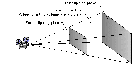
The viewing frustum is a 3-D volume in a scene positioned relative to the viewport's camera. For perspective viewing, the camera is positioned at the tip of an imaginary pyramid. This pyramid is intersected by two clipping planes, the front clipping plane and the back clipping plane. The volume in the pyramid between the front and back clipping planes is the viewing frustum. Only objects in the viewing frustum are visible.

The z-axis of the camera runs from the tip of the pyramid to the center of the back clipping plane. Your application can set and retrieve the positions of the front and back clipping planes by using the IDirect3DRMViewport2::SetFront, IDirect3DRMViewport2::SetBack, IDirect3DRMViewport2::GetFront, and IDirect3DRMViewport2::GetBack methods.
The dimensions of the viewport on the front clipping plane determine the apparent focal length of the camera's lens. (You can also think of this as a way to set the magnification of objects in the frustum.) To set and retrieve proportional dimensions for the viewport on the front clipping plane, use the IDirect3DRMViewport2::SetField and IDirect3DRMViewport2::GetField methods. To set and retrieve arbitrary dimensions for the viewport on the front clipping plane, use the IDirect3DRMViewport2::SetPlane and IDirect3DRMViewport2::GetPlane methods.
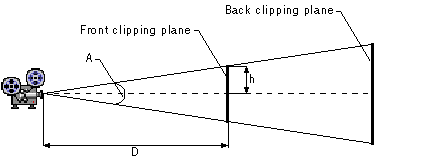
You can use the following equation to determine the relationship between the height (or width) of the front clipping plane and the viewing angle:
![]()
In this formula, the viewing angle is A, the front clipping plane is a distance D from the camera, and the height or width of the front clipping plane is 2h. If the device is not square, and thus the clipping planes are not square, the viewing angle is calculated using half the height or half the width of the front clipping plane, whichever is larger. The scale factors are set to the major axis of the device so you don't get distorted objects. If this is not what you want, you need to set uniform scaling.

The viewing frustum is a pyramid only for perspective viewing. For orthographic viewing, the viewing frustum is cuboid. These viewing types (or projection types) are defined by the D3DRMPROJECTIONTYPE enumerated type and used by the IDirect3DRMViewport2::GetProjection and IDirect3DRMViewport2::SetProjection methods.
Units of Measurement
DirectSound is the only module of DirectX where there is a default unit of measurement, the meter. This can be changed by the use of a distance factor. However, in both Direct3D Immediate Mode and Retained Mode there is no particular default unit. The developer must decide which units are most appropriate for the application, and build this into the program. For most applications measurements in meters, or feet, are appropriate, but for some they will not be. For example, if suns and moons are in the picture, distances could be measured in miles, or when modeling insects, or even atomic particles, the measurements might be very much less than a foot or a meter. DirectX simply works on the basis of "units" and has no concept of any real distance.
The absence of built in measurements can become a problem when importing DirectX files from a variety of sources. Not only is the measurement not included in the file, the "units" can be arbitrary, so need not be any standard measurement. This could make proper scaling of, say, two aircraft from different sources, difficult. If one model is in meters, and the other in feet, all that is needed is to scale one of the models when it is loaded. The IDirect3DRMMeshBuilder3::Scale function can be used in cases where the units of measurement of a model are known. Trial and error, or inspired guesswork, may be needed if a developer has little information as to the units used by the modeller.
If a developer wishes to use DirectSound, then setting the default measurement for the whole application to meters makes sense. For more information see the Units of Measure and Distance Factors section in the DirectSound documentation.
Transformations
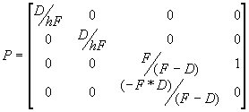
To render objects with 3-D coordinates in a 2-D window, the object must be transformed into the camera's frame. A projection matrix is then used to give a four-element homogeneous coordinate [x y z w], which is used to derive a three-element coordinate [x/w y/w z/w], where [x/w y/w] is the coordinate to be used in the window and z/w is the depth, ranging from 0 at the front clipping plane to 1 at the back clipping plane. The projection matrix is a combination of a perspective transformation followed by a scaling and translation to scale the objects into the window.
The following values are the elements of the projection matrix. In these formulas, h is the half-height of the viewing frustum, F is the distance from the camera, and D is the position in z-coordinates of the front clipping plane:

After projection, the next step is clipping and the conversion of x and y to screen-pixel coordinates within a viewport. Use the D3DVIEWPORT data members for this. The viewport is a rectangular window on the rendering surface.
typedef struct _D3DVIEWPORT {
    DWORD    dwSize;
    DWORD    dwX;
    DWORD    dwY;
    DWORD    dwWidth;
    DWORD    dwHeight;
    D3DVALUE dvScaleX;
    D3DVALUE dvScaleY;
    D3DVALUE dvMaxX;
    D3DVALUE dvMaxY;
    D3DVALUE dvMinZ;
    D3DVALUE dvMaxZ;
} D3DVIEWPORT, *LPD3DVIEWPORT;
The dwX and dwY fields specify the offset in screen pixels to the top left of the viewport on the surface.
The dwWidth and dwHeight fields are the width and height of the viewport in screen pixels.
The dvScaleX and dvScaleY fields are the scaling factors that are applied to the x and y values to yield screen coordinates. You would usually want to map the entire normalized perspective view volume onto the viewport using the following formulas:
  dvScaleX = dwWidth / 2
  dvScaleY = dwHeight / 2
X coordinates, for example, in the range of -1 to 1, will be scaled into the range of -dwWidth / 2 to dwWidth / 2. An offset of dwWidth / 2 is then added. This scaling occurs after clipping.
If the window is not square and you would like to preserve a correct aspect ratio, use the larger of the two window dimensions for both scaling values. You will also need to clip some of the view volume.
The dvMaxX, dvMaxY, dvinZ, and dvMaxZ fields specify the clipping planes: x = dvMaxX, x = —dvMaxX, y = dvMaxy, y = —dvMaxY, z = dvMinZ, z = dvMaxZ. To display all of the view volume, for example, you would set dvMaxX = dvMaxY = dvMaxZ = 1 and dvMinZ = 0. As noted above, if you want to preserve the correct aspect ratio on a nonsquare window, you will need to clip some of the view volume. To do so, use the following equations. These equations also work with square viewports, so use them all the time.
dvMaxX = dwWidth / (2 * dvScaleX)
dvMaxY = dwHeight / (2 * dvScaleY)
An application uses the viewport transformation to ensure that the distance by which the object is moved in world coordinates is scaled by the object's distance from the camera to account for perspective. Note that the result from IDirect3DRMViewport2::Transform is a four-element homogeneous vector. This avoids the problems associated with coordinates being scaled by an infinite amount near the camera's position.
For information about transformations for frames, see Transformations. For an overview of the mathematics of transformations, see 3-D Transformations.
Picking
Picking is the process of searching for visuals in the scene given a 2-D coordinate in the viewport's window. An application can use the IDirect3DRMViewport2::Pick method to retrieve either the closest object in the scene or a depth-sorted list of objects.
 Top of Page
© 2000 Microsoft and/or its suppliers. All rights reserved. Terms of Use.