Note The viewport structure used in DirectX 7.0 is much different than the structure recommended in previous releases (the legacy D3DVIEWPORT2 structure). Please read this information carefully to ensure that your application uses viewport parameters properly.
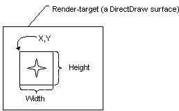
You define the viewport rectangle in C++ by using the D3DVIEWPORT7 structure. The D3DVIEWPORT7 structure is used with the viewport manipulation methods offered by the IDirect3DDevice7 interface: IDirect3DDevice7::SetViewport and IDirect3DDevice7::GetViewport. The D3DVIEWPORT7 structure contains four members—dwX, dwY, dwWidth, and dwHeight—that define the area of the render-target surface into which a scene will be rendered, called the "viewport rectangle".
These values correspond to the destination rectangle, or viewport rectangle, as shown in the following illustration.

The values you specify for the dwX, dwY, dwWidth, and dwHeight members of the D3DVIEWPORT7 structure are screen coordinates relative to the upper-left corner of the render-target surface. The structure defines two additional members (dvMinZ and dvMaxZ) indicate the depth-ranges into which the scene will be rendered.
The viewport structure used in DirectX 7.0 is much different than the structure recommended in previous releases (the legacy D3DVIEWPORT2 structure). In short, the D3DVIEWPORT7 structure simplifies the legacy structure by omitting the members that were used describe the size and dimensions of the viewport, in 3-D projection space. The vast majority of applications always set the now absent members to the same values, while a few used them to scale geometry to adjust for the viewport's aspect ratio. This effect was difficult to perform accurately and reliably.
Direct3D assumes that the viewport clipping volume ranges from -1.0 to 1.0 in X, and from 1.0 to -1.0 in Y (these were the settings used most often by applications in the past). In DirectX 7.0, as in previous releases of DirectX, you can adjust for viewport aspect ratio before clipping, during the projection transformation. This task is covered by topics in The Projection Transformation section.
Note The D3DVIEWPORT7 structure members dvMinZ and dvMaxZ are interpreted in a manner completely different than in previous versions of DirectX. The dvMinZ and dvMaxZ members now indicate the depth-ranges into which the scene will be rendered, and are not used for clipping. Most applications will set these members to 0.0 and 1.0 to enable the system to render to the entire range of depth values in the depth buffer. In some cases, you can achieve special effects by using other depth ranges. For instance, if you wanted to render a heads-up display in a game, you could set both values to 0.0 to force the system to render objects in a scene in the foreground, or you might set them both to 1.0 to render an object that should always be in the background.