| Platform SDK: DirectX |
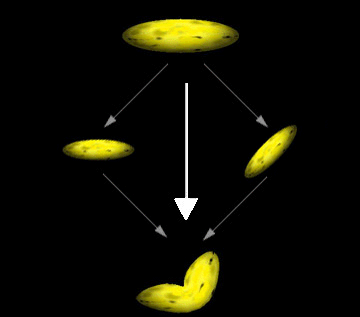
Direct3D Immediate Mode for DirectX 7.0 enables applications to increase the realism of their scenes by rendering segmented polygonal objects—especially characters—that have smoothly-blended joints. (These effects are often referred to as "skinning.") The system achieves this effect by applying additional "world" transformation matrices to a single set of vertices to create multiple results, then performing a linear blend between the resultant vertices to create a single set of geometry for rendering. The following image, based on the banana rendered by the Bend Sample, illustrates.

The preceding image shows how you might imagine the geometry-blending process. In a single rendering call, the system takes the vertices for the banana, transforms them twice—once without modification, and once with a simple rotation—and blends the results to create a "bent" banana. The system blends the vertex position, as well as the vertex normal (when lighting is enabled). Applications are not limited to two blending paths; Direct3D can blend geometry between as many as four different world matrices (including the standard world matrix, D3DTRANSFORMSTATE_WORLD).
Note When lighting is enabled, vertex normals are transformed by a corresponding inverse world-view matrix, weighted in the same way as the vertex position computations. The system normalizes the resulting normal vector if the D3DRENDERSTATE_NORMALIZENORMALS render state is set to TRUE.
Without geometry blending, dynamic articulated models are often rendered in segments. For instance, take a 3-D model of the human arm. In the simplest view, an arm has two parts: the upper arm which connects to the body, and the lower arm, which connects to the hand. The two are connected at the elbow, and the lower arm rotates at that point. An application that renders an arm might retain vertex data for the upper and lower arm, each with a separate world transformation matrix. The following code illustrates this.
typedef struct _Arm {
    D3DVERTEX upper_arm_verts[200];
    D3DMATRIX matWorld_Upper;

    D3DVERTEX lower_arm_verts[200];
    D3DMATRIX matWorld_Lower;
} ARM, *LPARM;

ARM MyArm; // This will need to be initialized.
To render the arm, two rendering calls would be made, as shown in the following code.
// Render the upper arm.
d3dDevice->SetTransform( D3DTRANSFORMSTATE_WORLD, &MyArm.matWorld_Upper );
d3dDevice->DrawPrimitive( D3DPT_TRIANGLELIST, D3DFVF_VERTEX,
                          MyArm.upper_arm_verts, 200, 0 );

// Render the lower arm, updating its world matrix to articulate the arm
// by pi/4 radians (45 degrees) at the elbow.
MyArm.matWorld_Lower = RotateMyArm(MyArm.matWorld, pi/4);
d3dDevice->SetTransform( D3DTRANSFORMSTATE_WORLD, &MyArm.matWorld_Lower );
d3dDevice->DrawPrimitive( D3DPT_TRIANGLELIST, D3DFVF_VERTEX,
                          MyArm.lower_arm_verts, 200, 0 );
Note When lighting is enabled, vertex normals are transformed by a corresponding inverse world-view matrix, weighted in the same way as the vertex position computations. The system normalizes the resulting normal vector if the D3DRENDERSTATE_NORMALIZENORMALS render state is set to True.
Without geometry blending, dynamic articulated models are often rendered in segments. For instance, take a 3-D model of the human arm. In the simplest view, an arm has two parts: the upper arm which connects to the body, and the lower arm, which connects to the hand. The two are connected at the elbow, and the lower arm rotates at that point. An application that renders an arm might retain vertex data for the upper and lower arm, each with a separate world transformation matrix. The following pseudo-code illustrates this.
Type Arm
    upper_arm_verts(200) As D3DVERTEX
    matWorld_Upper As D3DMATRIX

    lower_arm_verts(200) As D3DVERTEX
    matWorld_Lower As D3DMATRIX
End Type

Dim MyArm As Arm ' This will need to be initialized.
To render the arm, two rendering calls would be made, as shown in the following code.
' Render the upper arm.
Call d3DDevice.SetTransform(D3DTRANSFORMSTATE_WORLD, MyArm.matWorld_Upper)
Call d3DDevice.DrawPrimitive(D3DPT_TRIANGLELIST, D3DFVF_VERTEX, _
                             MyArm.upper_arm_verts, 200, 0)

' Render the lower arm, updating its world matrix to articulate the arm
' by pi/4 radians (45 degrees) at the elbow.
MyArm.matWorld_Lower = RotateMyArm(MyArm.matWorld, pi / 4)
Call d3DDevice.SetTransform(D3DTRANSFORMSTATE_WORLD, MyArm.matWorld_Lower)
Call d3DDevice.DrawPrimitive(D3DPT_TRIANGLELIST, D3DFVF_VERTEX, _
                             MyArm.lower_arm_verts, 200, 0)
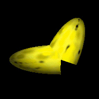
The following image is the banana from a version of the Bend Sample, modified to use this technique.

The differences between the blended geometry and the non-blended geometry are obvious. This example is admittedly somewhat extreme. In a real-world application, the "joints" of segmented models are designed such that seams aren't as obvious. However, ugly seams are visible at times, which presents constant challenges for model designers.
Geometry blending in Direct3D presents an alternative to the classic segmented-modeling scenario. Geometry blending isn't free; the improved visual quality of segmented objects comes at the cost of the blending computations during rendering. To minimize the impact of these additional operations, the Direct3D geometry pipeline is optimized to blend geometry with the least possible overhead. Applications that intelligently use the geometry blending services offered by Direct3D can improve the realism of their characters while avoiding serious performance repercussions.