Each disk consists of platters, rings on each side of each platter called tracks, and sections within each track called sectors. A sector is the smallest physical storage unit on a disk, almost always 512 bytes in size.
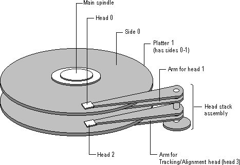
Figure 17.1 illustrates a hard disk with two platters. The remainder of this section describes the terms used on the figure.

Figure 17.1 Illustration of a hard disk
The cylinder/head/sector notation scheme described in this section is slowly being eliminated. All new disks use some kind of translation factor to make their actual hardware layout appear as something else, mostly to work with MS-DOS and Windows 95.
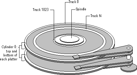
On hard disks, the data are stored on the disk in thin, concentric bands called tracks. There can be more than a thousand tracks on a 3½ inch hard disk. Tracks are a logical rather than physical structure, and are established when the disk is low-level formatted. Track numbers start at 0, and track 0 is the outermost track of the disk. The highest numbered track is next to the spindle. If the disk geometry is being translated, the highest numbered track would typically be 1023. Figure 17.2 shows track 0, a track in the middle of the disk, and track 1023.
A cylinder consists of the set of tracks that are at the same head position on the disk. In Figure 17.2, cylinder 0 is the four tracks at the outermost edge of the sides of the platters. If the disk has 1024 cylinders (which would be numbered 0-1023), cylinder 1023 consists of all of the tracks at the innermost edge of each side.

Figure 17.2 Tracks
Most disks used in personal computers today rotate at a constant angular velocity. The tracks near the outside of the disk are less densely populated with data than the tracks near the center of the disk. Thus, a fixed amount of data can be read in a constant period of time, even though the speed of the disk surface is faster on the tracks located further away from the center of the disk.
Modern disks reserve one side of one platter for track positioning information, which is written to the disk at the factory during disk assembly. It is not available to the operating system. The disk controller uses this information to fine tune the head locations when the heads move to another location on the disk. When a side contains the track position information, that side cannot be used for data. Thus, a disk assembly containing two platters has three sides that are available for data.
A head is a small transducer that can be positioned over a disk track by using a solenoid or servomotor. The head can change the properties of the magnetic media as it rotates underneath.
A specific area can be switched to either magnetic north or south, which corresponds to a binary state of 0 or 1. This series of binary information is the data stream the disk controller passes to and receives from the operating system.
There is one head for each side of each platter. The heads are normally attached to a common head-movement mechanism, so that the heads all move in unison. The heads are always positioned at the same logical track on each side of each platter.
Because disk tracks are concentric bands, the heads must move to the track that contains the data to be accessed. The moving of the heads from the current track to the track that contains the next data is called seeking. The heads are moved over the surface of the disk in small increments called steps. Each step corresponds to one track.
Each track is divided into sections called sectors. A sector is the smallest physcial storage unit on the disk. The data size of a sector is always a power of two, and is almost always 512 bytes.
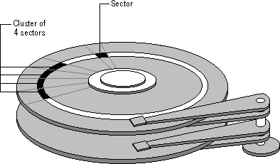
Each track has the same number of sectors, which means that the sectors are packed much closer together on tracks near the center of the disk. Figure 17.3, presented later in this section, shows sectors on a track. You can see that sectors closer to the spindle are closer together than those on the outside edge of the disk. The disk controller uses the sector identification information stored in the area immediately before the data in the sector to determine where the sector itself begins.
Note
On Multiple Zone Recording (MZR) disks, the number of sectors on each track is not the same across the entire disk, but the hardware makes the number appear to be the same. For more information, see the section titled "Multiple Zone Recording," presented later in this chapter.
The Windows NT file systems allocate storage in clusters, where a cluster is one or more contiguous sectors. Windows NT bases the cluster size on the size of the partition.
As a file is written to the disk, the file system allocates the appropriate number of clusters to store the file's data. For example, if each cluster is 512 bytes and the file is 800 bytes, two clusters are allocated for the file. Later, if you update the file to, for example, twice its size (1600 bytes), another two clusters are allocated.
If contiguous clusters (clusters that are next to each other on the disk) are not available, the data are written elsewhere on the disk, and the file is considered to be fragmented. Fragmentation is a problem when the file system must search several different locations to find all the pieces of the file you want to read. The search causes a delay before the file is retrieved. A larger cluster size reduces the potential for fragmentation, but increases the likelihood that clusters will have unused space.
Using clusters larger than one sector reduces fragmentation, and reduces the amount of disk space needed to store the information about the used and unused areas on the disk. Because the FAT file system can use only 16 bits for the cluster number, using clusters enables FAT volumes to be larger than 65,535 sectors. There is more information about the FAT file system presented later in this chapter, and in Chapter 18, "Choosing a File System."
Figure 17.3 shows a sector on one track and the grouping of four sectors into a cluster.

Figure 17.3 Sectors and clusters
Translation is the conversion of physical disk geometry (the number of cylinders on the disk, number of heads per cylinder, and sectors per track) to a logical configuration that is compatible with the operating system.
Since sector translation works between the disk itself and the system BIOS or firmware, the operating system is unaware of the actual characteristics of the disk. The disk could become inaccessible if the parameters used to set up the disk are lost, which can happen if the CMOS (described later in this section) or nonvolatile RAM (NVRAM) is corrupted or modified. In this case, the controller might translate to a configuration that adds up to the same total amount of disk space, but the operating system is not able to read data from the new arrangement. The disk has to be reformatted.
Many state-of-the-art disks now have a feature called Translation Mode. The disk controller queries the system BIOS (x86-based computers) or firmware (RISC-based computers) to determine the logical parameters the computer needs. If the number of cylinders, heads, and sectors per track the computer needs is within the range supported by the disk, the controller automatically configures itself to match those parameters. If the system BIOS or firmware does not support translation, the disk configures itself to its largest possible size, which is typically around 500 MB.
For example, all SCSI disks use some kind of translation, and many SCSI disks support hot swapping of sectors to fix bad sectors. This means that a SCSI disk maintains a set of unused sectors at the end of a disk. When a used sector goes bad, it is remapped to an unused sector and the data are written to the new sector. Windows NT uses absolute sector notation (also called logical sector notation, or LSN) for accessing disks. The translation of the sector number to the physical sector on the disk is handled by low-level disk device drivers and the hardware.
The translation is especially important when there are more than 1024 physical cylinders on the disk. The section titled "Using Hard Disks With More Than 1024 Cylinders (x86-based Computers)," presented later in this chapter, contains more details.
Some modern disks use MZR to solve the problem of wasted space on the outer tracks of the disk. The controller provides a layer of abstraction in disguising the physical layout of the sectors. The controller presents the disk to the system BIOS and the operating system as if each track had the same number of sectors per track.
MZR disks alter the operating frequency of the disk electronics, based on disk zones. Each zone is a contiguous group of cylinders. Using different frequencies means that each zone can have a different number of sectors per track. Since the zone frequency corresponds to the different data densities in each zone, the effect is to maintain a constant data density across the whole disk.
All this technology takes place entirely at the hardware level. The computer's operating system still sees the disk in the conventional logical layout of cylinders, heads, and sectors, where there is a constant number of sectors per cylinder.
When you format an MZR disk, you need to use the same parameters for sector size, tracks per cylinder, and sectors per track for all partitions.
The Complementary Metal Oxide Semiconductor (CMOS) chip in the computer stores information about the devices connected to the computer. When you install or change a non-SCSI disk in your computer, you need to use the BIOS setup program provided on your computer to update the information in the CMOS. (SCSI disks have their own configuration program, typically provided by the manufacturer.)
It is possible for the CMOS battery to run down if you do not turn your computer on for a long time. And the CMOS chip sometimes fails. See Chapter 21, "Troubleshooting Startup and Disk Problems," for information about identifying CMOS problems.