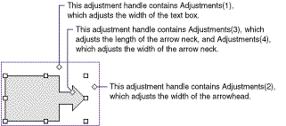
 Note Because each adjustable shape has a different set of adjustments, the best way to verify the adjustment behavior for a specific shape is to manually create an instance of the shape, make adjustments with the macro recorder turned on, and then examine the recorded code.
The following table summarizes the ranges of valid adjustment values for different types of adjustments. In most cases, if you specify a value that's beyond the range of valid values, the closest valid value will be assigned to the adjustment.
| Type of adjustment | Valid values |
| Linear (horizontal or vertical) | Generally the value 0.0 represents the left or top edge of the shape and the value 1.0 represents the right or bottom edge of the shape. Valid values correspond to valid adjustments you can make to the shape manually. For example, if you can only pull an adjustment handle half way across the shape manually, the maximum value for the corresponding adjustment will be 0.5. For shapes such as connectors and callouts, where the values 0.0 and 1.0 represent the limits of the rectangle defined by the starting and ending points of the connector or callout line, negative numbers and numbers greater than 1.0 are valid values. |
| Radial | An adjustment value of 1.0 corresponds to the width of the shape. The maximum value is 0.5, or half way across the shape. |
| Angle | Values are expressed in degrees. If you specify a value outside the range – 180 to 180, it will be normalized to be within that range. |
Set myDocument = ActivePresentation.Slides(1)
Set rac = myDocument.Shapes.AddShape(msoShapeRightArrowCallout, 10, 10, 250, 190)
With rac.Adjustments
    .Item(1) = 0.5    'adjusts width of text box
    .Item(2) = 0.15   'adjusts width of arrow head
    .Item(3) = 0.8    'adjusts length of arrow head
    .Item(4) = 0.4    'adjusts width of arrow neck
End With