Each hardware resource is represented by a cube, evoking the physical presence of the equipment within the system. Any system can be described by a small number of deployment diagrams, and a single diagram is often sufficient.

The nature of the equipment may be specified using a stereotype. The following example proposes three stereotypes to distinguish devices, processors, and memory. If necessary, the user has the possibility of defining other stereotypes.

The difference between a device and a processor depends strongly on the viewpoint. A terminal
will be seen as a device by the terminal user, while it will correspond to a processor for the developer of a server X
that executes on the embedded processor contained in X
.X
The various nodes that appear in the deployment diagram are connected to each other by lines representing a communication infrastructure, which is a priori bidirectional. The nature of that infrastructure may be specified using a stereotype.

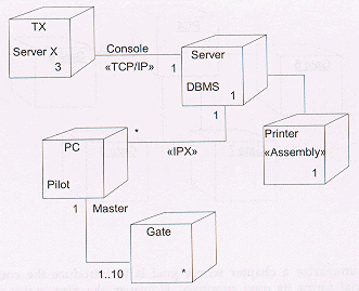
Deployment diagrams may show node classes or node instances. As with other types of diagram, the graphical difference between classes and objects is implemented by underlining the object name. The following example shows the deployment diagram of a building access management system:

The presence of multiplicity and role information shows that the diagram represents classes of nodes. The diagram shows a system composed of a server with surrounding PCs that drive the opening and closing of gates. The number of PCs has not been established. Conversely, it appears that every PC may control at most 10 gates. Three X-terminals play the role of console to access the system. A printer is connected to the server.
The diagram describes the nature of the communication links between the various nodes. The server and the PCs are connected via an IPX link; the X-terminals and the server communicate via TCP/IP. The nature of the connections between other nodes is not specified.
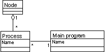
Nodes corresponding to processors from the application's standpoint — the «processor» stereotype does not forcibly appear in the deployment diagrams — also hold the name of the processes they contain. The server executes a database management system, and the PC houses the driver software that drives and controls the gates. The names of these processes facilitate the linking between the deployment diagram and the component diagram. Each process named in the deployment diagram executes a main program with the same name as the one described within the component diagram.

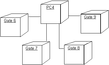
Deployment diagrams may also exhibit node instances (identified by underlined names). The following diagram gives us precise information concerning the situation with respect to the system site deployment. It appears that gates 6, 7, 8 and 9 are driven by PC4:
