Although it may sound old-fashioned, it can be very valuable to write the name of each object that we listed on to a small card or piece of paper, one note per object. Then we can use a white-board, or any other large surface we can draw on, and stick the objects to the surface. This lets us move the objects around as needed, and lets us draw lines between the objects to show how they're connected.
There are commercial case tools on the market that make this very easy to perform on a computer. Rational Rose for Visual Basic and Microsoft Visual Modeler are good examples. These programs can be very useful, as they offer the same abilities as putting cards on a white-board, but allow us to save the diagrams to disk, add comments to our objects and relationships, and sometimes even generate code based on the object design.
Once our objects are written down and placed on a surface, we're ready to move on and figure out how they relate to each other. This is fairly straightforward, since all we need to do is go back through the use case and look for verbs and other connecting phrases between the nouns. Again, this could get carried to an extreme, so some judgement is required!
There are some key types of relationships that we need to find. Other relationships exist, and are important, but these are ones we need to make sure we get:
| Relationship | Description/Example |
| Ownership (owns, has) | Parent-child relationships |
| User (uses) | One object uses or employs the services of another object |
| Aggregate (contains, made of) | One object is made up of other (subordinate) objects |
| Generalization (is a) | One object is a specific type of another object |
Something else to keep in mind is that we might need to add some new objects as we go along. Picking out the nouns from the use case is great, but the use case might have implied some other objects that we don't have yet. For instance, we may find that we need objects to represent some of the verbs in our use cases. That's fine, just don't be surprised if it happens.
Following the same logic, there will be objects that we don't need, and we'll be getting rid of those.
So let's look through the use case and pick out some relationships:
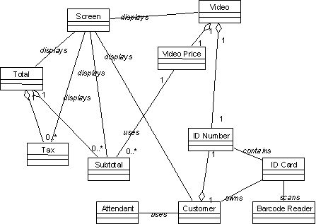
There are other relationships that we could identify; these are just some examples that illustrate the common relationships we'll encounter. This information is more clearly presented in diagrammatic form:

The figure shown here was drawn using Microsoft Visual Modeler, part of the Visual Studio package. The notation used is the Universal Modeling Language (UML). Appendix B contains a brief explanation of UML as used here.
Now the challenge is to eliminate the objects that we don't need to put into our software model. There are two main things to look at:
The first thing we should do is look at those objects that don't have a lot of relationships in the diagram. Neither the attendant nor the barcode reader are well connected, so they need to be looked at carefully.
It's unlikely that we'll need to have an attendant object to handle the functionality in this use case, since the attendant just interacts with the screen. We won't completely write it off as an object, however, because it was also listed in the requirements use case - so it may be used to provide some other functionality. Still, we don't need it here, so we can remove it from our diagram.
The barcode reader is probably not required either. This is more of a common sense issue, but barcode readers usually just provide input to the software that's indistinguishable from keyboard input, so it's hard to imagine what such a business object would do for our program.
Now look at the objects that the attendant and barcode reader touched. The screen object is still very connected, but the ID card is a borderline case. Since the ID card is just a way of expressing the customer's ID number, we can probably eliminate it from the picture as well.
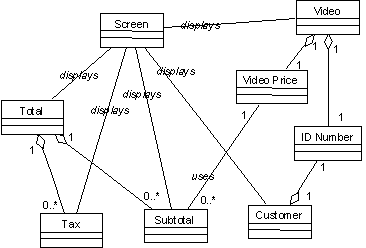
The next step is to look at each object and eliminate those that belong in either the presentation or data processing layers of the application. In our case, the screen object certainly fits the bill for belonging in the presentation layer.
However, it's very useful to leave something representing the presentation layer in the model, for the sake of clarity. At the same time, we don't want to mistake it to be an actual business object, so we need to keep that in mind when we look at the figure.
After all the changes, our diagram looks like this:

At this point, we've got a pretty clear picture of the objects that we need, and how they're all related to each other. Now is a good time to look at the diagram with a critical eye to determine if there are objects that can be consolidated to form a more general object.
There may also be objects in our diagram that are really attributes of other objects, but we won't worry about those yet. We'll discuss attributes and properties in the next section.
Looking at the diagram, there are three objects that are all very much interrelated. The tax and total objects are both generated upon the basis on the subtotal object. It would make a lot of sense to add a new object to the diagram that would give us a more general view of these objects.
If we look back at our requirements use case, we'll see that there is a potential business object called an invoice.
It is important to keep looking back at the requirements use case, and to look at all the other related functional use cases, to find objects that overlap or have relationships with the objects at hand. Our functional analysis is not happening in isolation, so it's important to regularly stop and take a look at the bigger picture.
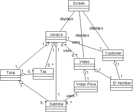
The invoice object needs to display the total amount along with some other information, so it's a good candidate to use as an object to contain the total, tax and subtotal objects. Here's a list the relationships for our new invoice object:
Looking back at the previous example, we can see how complex the model is for the presentation designer. The screen entity is communicating with a lot of different objects in our model, so it may be very difficult for the programmer of the presentation layer to use our model effectively. In this new model, however, the UI developer only needs to worry about interacting with three objects: invoice, video and customer. All the other objects are available through one of those three.
If we add in the invoice object, we end up with the following diagram for our objects:

At this point, we have a pretty good understanding of the business objects that we need to handle for the functional use case. We may not be done yet, however: it's possible that we'll still need to add or remove some objects as we finish up the analysis.
Now we need to move on to figure out some specifics about the objects; in particular, we need to list the properties, methods, and events that each object needs in order to support the use case's functionality. First, let's look at the properties.