This article may contain URLs that were valid when originally published, but now link to sites or pages that no longer exist. To maintain the flow of the article, we've left these URLs in the text, but disabled the links.


MIND


This article assumes you're familiar with Internet basics.

The ABCs of TCP/IP
Marco Tabini

The Internet is based on TCP/IP, a protocol that originated years before there was an information superhighway. But what does TCP/IP really do?
You probably already know that the Internet grew from a small military project during the sixties into the largest computer network in the world. When the ARPANet project kicked off almost thirty years ago, its goal was to create a distributed and decentralized computer network for the defense community. If an enemy destroyed a strategic command center, others would be able to keep on working to ensure the security of the nation. Needless to say, network connectivity was limited. If you think that connections are slow today, in those days a 300 bps connection was a luxury that only large organizations (like the government) could afford.
      TCP/IP was the set of protocols developed to provide transmission and addressing for these connections. (You need to know two important things on a network—what you're sending and where it's going.) Surprisingly, the underlying structure of the ARPANet (which eventually became what is called the Internet) was fundamentally the same then as it is today, and so are many of the protocols widely used in network applications. This makes TCP/IP a pretty amazing and adaptive suite of protocols.
      Change has been sporadic because of the increasing complexity of the Internet itself. It's one thing to order a bunch of military sites to change their firmware; it's another thing entirely to convince millions of unrelated people to spend money upgrading all their systems. While backwards compatibility is a generally acceptable compromise in the case of high-level protocols (such as HTTP), low-level protocols do not benefit from this kind of solution because of their strategic role in the exchange of information. Consider what would happen if a new protocol revision changed the number of bits used for IP addressing as an optional implementation. All of a sudden, computers that do not comply with the specification would be unable to access machines that do. This would be big trouble.

The Multilayered Internet Cake
      The Internet is known to be a medium that relies on many communication systems. If you connect to the net from home, your data will travel across a phone line, whereas your computer at work probably relies on a high-speed Ethernet or Token Ring network.
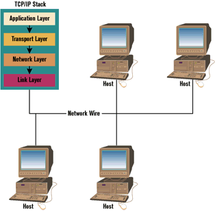
      To provide this level of flexibility, TCP/IP works on a system of layers, each of which controls a single aspect of data transmission. As you can see in Figure 1, data originating from the application layer has to move through four logical layers before being poured on the network wire or whatever medium is used to physically transmit information.

Figure 1: TCP/IP Layers


      The transport layer takes care of the flow of data between two network hosts. The network layer controls how data is moved around in the network. For example, it establishes what route a particular packet must follow to move from host A to host B, and provides a method for identifying hosts in a unique way. The link layer sends and receives data over the physical medium chosen for the transmission of information. The important part of this surprisingly simple scheme is that every layer in the chain treats the information received from or destined to the higher-level layer as pure data. This means that each layer is virtually independent from the others and its implementation can be arbitrary. Thus, as long as the link layer pours data onto the wire, the other layers are not affected in any way by its implementation, and vice-versa.
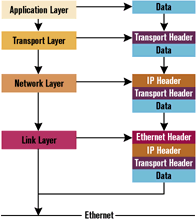
Figure 2: Data Encapsulation


      To better understand the way this works, take a look at Figure 2. During a send operation, each layer encapsulates all the information sent by the previous one with a series of headers. During a receive operation, these headers are peeled off the data chunk one by one so that only the relevant data reaches the application layer. Keep in mind that a packet can contain data destined for someplace other than the application layer. In that case, the processing of information stops when no more data is available.
      TCP/IP uses two transport protocols: Transmission Control Protocol (TCP) and User Datagram Protocol (UDP). TCP provides a reliable, connection-based transmission channel; it takes care of breaking large chunks of data into smaller packets, suitable for the physical network being used, and guarantees that data sent from one end is received on the other. UDP, on the other hand, is a connectionless protocol and does not guarantee the delivery of data sent, thus leaving the whole control mechanism and error-checking to the application itself. Most networking programs and application-layer protocols, such as HTTP or FTP, rely on TCP because it is easy to implement and provides most of the traffic control operations. However, there are cases in which UDP works better, particularly when data delivery is of little or no importance. DNS and the old Talk protocol are partly based on UDP, and it's the choice of many streaming formats like NetShow.

It's Ethernet, but Not Forever
      Ethernet is probably the most common type of LAN on the Internet. Chances are, unless you are particularly lucky and can afford a Token Ring connection, your office will be interconnected using a Ethernet network, too.
      The Ethernet standard was developed by IBM, DEC, and Xerox, and was published in 1982. It can reach speeds up to 100 Mb/s, and revolves around a protocol known as Carrier Sense, Multiple Access with Collision Detection (CSMA/CD). In the basic design principle of Ethernet, the wire is considered one large pipe, to which every host has access at the same time and on the same level. When a network card has a packet to send, it waits until the pipe is available and then tries to send its own data. If another network card tries to do the same thing concurrently, a collision occurs; both cards abort the transmission and retry after a random amount of time. The randomization of the retry interval ensures that if two packets collide, they will not be resent at the same time again.
      Needless to say, collisions are bad for your LAN. When they occur, the network stops working—even if for a short amount of time—and its efficiency decreases. Collisions can be caused by many factors, including the number of hosts on the network and the quality of the cabling, and they can affect throughput performance even with minimal amounts of bandwidth usage.
      As the Ethernet implementation considers the wire to be one shared data pipe, data has to be divided in chunks of an appropriate size to guarantee an even bandwidth usage to all hosts on the network. This way, each host will only send packets of up to a predefined number of bits, allowing every other network card to participate in the transmission of data. The maximum size that a packet can assume is characteristic to each specific network implementation, and is called Maximum Transmission Unit (MTU). For Ethernet, this value is 1,500 bytes.
      The division of information in packets makes it also possible to implement an efficient error control system. When a network card sends a packet, a Cyclic Redundancy Check (CRC) value is attached to it. Once the destination host has received the packet, it recalculates the CRC and checks it against the one attached to the packet. If they do not match, the packet is discarded.

Internet ZIP Codes
      As all hosts on an Ethernet network share the same data pipe, they also receive all the traffic that travels across the wire. For identification purposes, every network card is assigned a 32-bit hardware value known as its MAC address. Whenever a packet is sent across the network, the software in the link layer envelops it in an Ethernet datagram that contains the MAC address of the destination machine. Once on the wire, the packet is received by all the hosts on the LAN, but only the one with the MAC address specified in the destination field will actually process it.
      Almost all cards now support a special working status, called promiscuous mode, that bypasses the MAC address filtering process and processes all the packets that it receives, regardless of the destination address. Promiscuous mode is the foundation of apps known as network analyzers or packet sniffers that allow a host to monitor all the traffic on its network—for diagnostic purposes, of course.
      Since this hardware addressing model is specific to Ethernet, it is not suitable as a general system for uniquely identifying hosts on a WAN that is based on several networking systems. Remember, the network layer is completely independent from the link layer, and therefore it doesn't know what hardware addresses are.
      To solve this problem, TCP/IP implements Internet Protocol (IP) addressing. I am sure that you are familiar with numeric IPs, usually expressed in the well-known dotted decimal notation:

 www.xxx.yyy.zzz
Each of the fields in an IP address is an 8-bit integer. These 32-bit addresses perform a function that is very similar to hardware addresses, but they work across Token Ring, fiber-optic, and even phone networks just as well.
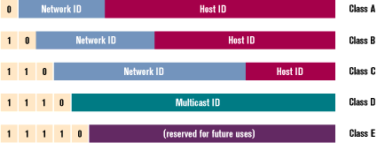
      The structure of an IP address is shown in Figure 3. As you can see, the first few bits (up to five) determine what class an address belongs to. With the exception of multicast addresses, the class type tells you how many bits are used to identify a specific LAN (Network ID) and specific hosts inside that network (Host ID). The more addresses a network needs, the higher its assigned class level. But more address space means less efficiency in message routing. Thus, a class A network can contain about 224 hosts, while a class B network can contain up to roughly 216. In most cases, however, only class C networks, with 28 possible hosts, are efficiently usable, because only very few organizations worldwide have a need for more than 254 addresses.
Figure 3: IP Address Structure

      A few network spaces have been reserved for particular uses. The class A network 127.xxx.yyy.zzz, for example, is used for the internal loopback interface; any packet sent to the address 127.0.0.1 is automatically redirected from the send queue to the receive queue, without ever even reaching the link layer.
      IP supports three types of addressing. In the simplest case, when a packet has to be sent to a specific host whose address is known, unicast datagrams are sent. These can be considered person-to-person calls in the sense that (at least in theory) no other host on the network should be interested in processing that data. When a host wants to send a datagram to all its counterparts on the network, a multicast packet is sent to the special address 255.255.255.255. IP will expect that packet to be delivered to all the hosts on its local network.
      Multicast datagrams are supposed to be delivered to a specific group of hosts. Multicast has been designed primarily for connectionless environments where one server has to send a stream of data to several clients with minimal bandwidth usage. During a normal TCP session, each client has to establish a separate connection to the server. At the same time, the server has to send the same data to each client independently, thus limiting the maximum number of clients that can be served due to bandwidth restrictions. Using multicast technology, only one copy of the data is sent out to a group of hosts, and that packet is routed through the Internet until it reaches every member of that group.
      Given the proper conditions, multicast is a terrific improvement over unicast for certain applications, such as audio or video streaming or push technologies. However, the Internet community has consistently ignored it for a long time; it's difficult to implement and it's almost unsupported by any major network programming libraries. Due to increasing interest in streaming technologies and the requirement of a more bandwidth-friendly transmission system for multimedia-intensive applications, some vendors are beginning to develop multicast-based solutions. A server running Microsoft® NetShow™ 2.0 (or higher), for example, is capable of transmitting high-quality audio and video over the Internet with very limited bandwidth usage.

Mind the Gap
      Since hardware and IP addressing are based on two completely different systems, how does the link layer know how to deliver a packet that the network layer sent to a particular IP address? The answer to this daunting question is in the Address Resolution Protocol (ARP), which makes it possible to convert IP addresses to hardware addresses in a distributed environment. Here is how a typical ARP session works.
      When a host needs to send a packet to another host, it first looks into its ARP cache; this contains IP/hardware address correspondences collected during previous activity. If the cache does not contain an entry for the destination host, the network driver sends an Ethernet broadcast message known as an ARP query (with the destination address 0xFFFFFFFF). This message basically means, "Does anybody who receives this message have a hardware address for this IP address? If you do, please send your answer to me." The source host sets a timeout to two seconds and waits for a response. Every host that is on the network receives the message and stores an entry in its ARP cache for the source host. This will avoid another ARP handshake if there's future activity between the two hosts. It then looks up the IP address. If a correspondence is found, the host generates an ARP response and sends it back to the original host. Back on the host, if no answer is received within two seconds, a new query is generated and sent to the network. This time, however, the timeout value is doubled to four seconds. This mechanism is repeated at every timeout until either a response is received or a maximum timeout value is reached. If a response is received, the original host creates an entry in its cache for the destination host and, finally, sends the packet over to it.
      The ARP cache is reinitialized every time a host is booted, so it has to be rebuilt every time. In some cases, on a network in which IP addresses are not statically assigned—for example, if Dynamic Host Control Protocol (DHCP) is in use—it is possible for entries in the ARP cache to become obsolete when a host is assigned a new IP address but no other host on the network knows yet. To overcome this problem, every host issues a gratuitous ARP request for its own IP address every time it boots. This accomplishes two goals. First, this broadcasts the host's hardware address to the other hosts on the network. (Remember, when a query is sent, every host on the network creates or updates an entry in its ARP cache for the source host.) Second, this makes it possible to detect an address collision, which occurs whenever two hosts are assigned the same IP address. If this occurs, the source host will receive an ARP response where the source and destination MAC addresses are the same, but are different from its own. (This MAC address indicates the machine that already owns the IP address.)
      ARP is used only on networks where there is no preferential connection between one host and another. On Ethernet, where all the computers share the same cable, it is impossible to know if a certain computer is connected to the network, and ARP becomes indispensable. On the other hand, a PPP or SLIP connection does not have this problem, since only two hosts are involved in the connection and they know each other's IP addresses.

When the Gap is Bigger
      Now for the fun part: what happens if the host that you want to send a packet to is not on your local network? A special class of hosts, known as routers, comes into play. A router is simply a host that forwards packets between two or more different networks to which it is connected, thus making it possible, for instance, to send data through the Internet.
      A router, by design, does not forward broadcast messages, therefore limiting ARP's scope to a local network. However, routers do listen to ARP requests, and when they find a request that has been sent twice (because the issuing host timed out on the first try), they evaluate whether the destination address belongs to a nonlocal network. If it does, the router sends a fake ARP response, pretending to be the destination host itself. This will cause the originating host to send all data packets to the router, which can then redirect them across the other network.
      The destination host might be on a network that the router is only connected to through a series of other routers, thus making direct delivery of the packet impossible. In this case, the first router ends up sending the packet to the next router in the chain through this same forwarding method.
      A router makes forwarding decisions based on a local database—or routing table—that contain correspondences between ranges of addresses and different networks. In addition to statically determined routing tables, IP supports dynamic routing, which allows the system to modify the tables in response to changes in the routing environment, such as faulty routers, network interruptions, and so on. The most widely used dynamic routing protocol is the Routing Information Protocol (RIP), which is supported by almost all the implementations of TCP/IP, including the one used by Windows NT®. When RIP is enabled, adjacent (directly connected) routers talk to each other and periodically exchange information regarding the networks to which they are connected. When one of the routers fails to update its information, the others consider it dead and delete the corresponding entry from their routing tables.
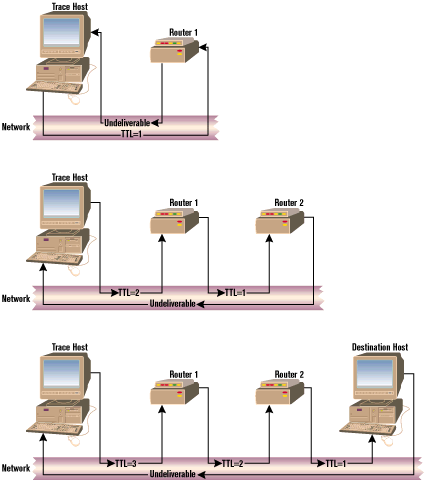
      To avoid infinite loops in which, for example, two routers point to each other for a given range of addresses, each packet on the network is given a Time To Live (TTL) value, originally intended to express the maximum number of seconds that the data was supposed to be on the network. The TTL value, however, is commonly implemented as the maximum number of routers—or hops—that the packet goes through before being dropped. Whenever a router receives a packet with a TTL of 0 or 1, it does not forward it and sends a "time exceeded" message to the originating host.

Figure 4: Tracert in action

      The TTL value is the key to the popular tracert program, whose working principle is shown in Figure 4. Tracert sends a packet of data to a given host, starting with a TTL of 1 and increments it by one until the host is reached, thus receiving "time exceeded" messages from every router that is encountered by the packet on its way. Since every IP message carries the IP address of its sender, tracert can output the exact path followed by the packet to its destination. This program is very useful for finding faulty routers on the Internet and working around them.

Moving Up
      Let's now move on to the transport layer. As mentioned earlier, TCP/IP-based applications can use two protocols for communicating with each other. UDP, by far the simpler and lighter, provides a connectionless transmission protocol. This means there are no guarantees that data sent on one end is delivered to the other—or that there is another end at all, for that matter. Since no reliable communication channel has to be established and maintained, however, UDP makes for a very efficient and lightweight transmission protocol, especially suitable for streaming systems such as video or audio applications. Ironically, most audio and video programs do not support UDP as their primary communication method. In contrast with UDP, TCP provides a reliable, connection-based transmission protocol. All data sent through TCP has to be confirmed by the destination host—and TCP knows that the host exists!
      As mentioned earlier, the MTU of a certain medium determines how much data can be transferred through it at a time. For larger transfers, the data must be divided in packets of a given size and sent one packet at a time. For a protocol like TCP, for which reliability is so important, this poses a potential problem.
      Let's consider a typical network scenario. Host A sends three packets to host B. Unfortunately, the second packet is corrupted and removed by the link layer because its CRC fails. The TCP driver on host B, therefore, receives packets 1 and 3 and, without any means for safely identifying the correct position of every packet in the sequence, is not able to determine that some data is missing—let alone guarantee the reliability of the connection!
      To ensure that all the packets are delivered properly, host A attaches a sequence number to all the packets it sends out. The sequence number is increased by one every time a new packet is sent. On the other end, host B is now able to determine that one packet is missing and acts accordingly.
      The first step in establishing a TCP connection must be, therefore, synchronizing the sequence numbers between the two hosts so that each one knows how to organize the packets. To establish a TCP connection, host A sends a SYN (synchronize) message to host B. When the message arrives at its destination, host B sends back a packet containing an ACK (acknowledge) message and a SYN message containing the original sequence number sent by host A plus 1 (remember, this is the second packet in the sequence). When host A receives the packet, it has a chance to verify that host B is reachable and that the initial sequence number was not corrupted during the transmission. To conclude the connection sequence, host A sends an ACK message to host B in a packet marked with the initial sequence number plus 2.
      This exchange of information is often referred to as the three-way handshake. TCP even covers the remote possibility that two hosts might try to connect to each other at the same time. In this case, the protocol implementation only needs to exchange one more packet than the normal three to detect and recover from the situation. Pretty efficient, eh?
      Closing a TCP connection needs a little more work. Host A, which wants to close its connection to host B, sends a FIN (host finished sending data). Once host B receives the packet, it notifies the application that was using the connection and sends an ACK message to host A. The application then needs to close the connection on its end, causing host B to send a FIN packet to host A, which in turn responds with an ACK. Since this is a full-duplex connection, the double closure is needed; each party can send data independently from the other and both communication channels need to be shut down independently.
      Transmission of data over a TCP connection occurs through a send-and-acknowledge method. Host A sends packets of data to host B, which in turn acknowledges them, thus informing its counterpart that the transmission was successful. Host A sets a timeout value after which it resends packets of data that have not been acknowledged by host B. It is important to understand that the acknowledgment of packet reception is not done on a one-by-one basis, but rather cumulatively for all packets up to the one that is being acknowledged. If no data flow-controlling mechanism is in place, the corruption of one packet could potentially force host A to resend a large number of packets.
      To avoid such a problem, TCP implements a system known as "sliding windows." Imagine the data to be sent from host A to host B as a long line of packets. Before the beginning of the transfer, host B advertises the size of its receiving window—the buffer designed to receive data. Host A sets a sending window of the same size and sends just enough packets to fill it, then stops and waits for the acknowledgment of at least a part of the data sent. As ACK messages are received from host B, the sending window slides forward in the data line until all packets have been transmitted. If one bad packet is detected by the timeout mechanism, the maximum amount of data that can be lost corresponds to the size of the receiving window, thus maximizing throughput and minimizing bandwidth usage.

Reaching the Top
      The final layer of the TCP/IP stack is the application layer, where both server and client applications that use TCP/IP reside. Most of these programs use an API that is derived from the Berkeley Sockets API, originally available on the BSD operating system. On the Windows® platform, it's known as WinSock. The Sockets API works by assigning an identifier, known as a socket, to a given host port. Applications can use sockets to open a TCP connection, send and receive data using both TCP and UDP, and use the Domain Name System to match human-friendly alphanumeric addresses (such as microsoft.com) into IP addresses (like 157.57.60.23) and vice-versa.

Where to Go from Here
      TCP/IP is a complex topic. Entire books have been written about single aspects of its implementation. This article only scratches the surface, as its goal is to give Web developers an idea of what they are working with. Here are a few resources that can give you added insight to this topic.
      The Request For Comment (RFC) documents are the very foundation of TCP/IP, as they describe the standards on which it's based. There are well over two thousand of them, but only a small part really matter. All RFCs can be found at the InterNIC Web site(http://www.internic.net) and can be searched using a variety of tools from that site.
      W. Richard Stevens's three volume TCP/IP Illustrated series (Addison-Wesley) is an excellent starting point for learning about TCP/IP. The good thing about this series is that the author shows you exactly what happens on the network when a particular operation occurs through the use of the Unix tool tcpipdump.
      If you are planning to become a Microsoft Certified Systems Engineer, you might want to take a look at Microsoft TCP/IP Training (Microsoft Press, 1997), which will prepare you for the Microsoft TCP/IP exam. This book can help you understand how TCP/IP is implemented in Windows NT. You'll find it surprising—in a good way—how well the Microsoft implementation of TCP/IP complies with the official RFCs.

Also see the sidebar: The Future of the Internet Protocol

From the October 1998 issue of Microsoft Interactive Developer.