Windows 98 supports standards for the following types of hardware devices: HID, DVD, Digital Audio, Still Image, Multiple Display Support, Video Capture, and Accelerated Graphics Port (AGP). Much of this support is either new or significantly improved over what was offered under Windows 95. For Windows 98, driver support is mostly WDM-based, which means the same set of drivers will also be used in future versions of Windows NT. The following sections describe the hardware device standards supported by Windows 98.
Windows 98 supports devices compliant with the Human Interface Device (HID) firmware specification, the new standard for input devices, such as keyboards, mouse and pointing devices, joysticks, gamepads, and other types of game controllers. Support is based on the specification developed by the USB Implementers’ Forum and is targeted towards devices connecting through USB. The HID-compliant device is self-describing, indicating its type and providing usage information when plugged into the host system.
For more information about the USB Implementers Forum, see http://www.usb.org/. The HID specification is also available at this Web site.
Under Windows 98, HID keyboards, mouse devices, joysticks, and gamepads that plug into USB are connected to the existing legacy input device infrastructure. This is done through a set of VxD-to-WDM mappers that map the HID data into the corresponding legacy format. This allows the operating system and existing applications to receive data transparently from these kinds of USB/HID devices.
In general, communication with HID devices is Win32 File I/O-based, and devices can be accessed in both kernel mode and user mode. Devices that connect through USB are Plug and Play and power-managed in accordance with the OnNow specification for input devices.
Windows 98 provides, through the built-in USB and HID drivers stacks and the HID parser, complete support for any HID-compliant device. Third-party drivers and applications can enumerate, open, and exchange data with any HID device and have this data parsed by the built-in HID parser. In addition, Windows 98 includes complete support for the following types of standard HID input devices:
These types of HID devices can be plugged into the system and be used immediately. They do not require installation of additional software drivers.
The generality of the HID specification opens up the opportunity for new kinds of input devices. For example, HID usage pages and usages are defined for the following types of devices:
For more information about HID usage, see the supplemental HID Usages Table specification at http://www.usb.org/.
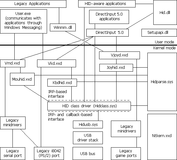
The HID class driver (Hidclass.sys), the USB-specific HID class minidriver (Hidusb.sys), and the HID kernel-mode parser (Hidparse.sys) comprise the heart of the Windows 98 HID architecture. The HID architecture in Windows 98 is shown in Figure 30.5.

Figure 30.5 HID architecture
The following HID modules are shown in Figure 30.5:
As in Windows 95, legacy VxD style minidrivers connect Vmd.vxd with the serial and PS/2 ports, and connect Vjoyd.vxd with the game ports.
Plug and Play and power management support for USB/HID devices takes place within the USB driver stack that is part of the new WDM-based architecture.
From an application perspective, any HID device can be accessed either through HID APIs exposed by Hid.dll, or through DirectInput COM methods. DirectInput, which is part of Microsoft’s DirectX multimedia architecture, now includes support for HID devices.
Windows 98 also supports HID devices that connect to the system through ports or buses other than those of Hidusb.sys. For example, the IEEE 1394 bus can be developed and supplied by vendors. Vendors can also extend or modify the functionality or data of devices by inserting filter drivers into the USB or HID driver stacks.
For more information about minidriver and filter-driver development, see the WDM DDK.
DVD as an official product name is not an acronym. It is a branded, trademarked name owned by the DVD Consortium. As an acronym, DVD has various interpretations, including Digital Versatile Disc and Digital Video Disc, but these letters have come to represent more than just an acronym. As a natural enhancement of CD-ROM, DVD provides the new generation of optical-disc storage technology for a huge array of both consumer electronics and personal computer devices. DVD provides digital data storage that encompasses audio, video, and computer data, and therefore has the potential for replacing current technologies for business data storage, laser disc, audio CD and CD-ROM, VHS videotape, and dedicated game technologies. DVD was designed from the ground up for multimedia applications, with a key goal of being able to store a full-length feature movie.
The DVD Consortium has defined two major compression technologies, MPEG-2 and AC-3, to be used to store over two hours of video and audio on a single DVD disk. In addition, the quality of the stored video and audio is higher than that found on laser disks and CDs, opening up new possibilities for content providers.
Windows 98 supports DVD as follows:
DVD movie playback.
If the proper decoding hardware or software is present, Windows 98 supports full DVD-Video playback This support is especially important for entertainment computers, but it is also important for any multimedia hardware platform meant to provide good quality support for the playback of movies. This support includes the full range of interactivity and high-quality playback found on a standard DVD-Video player. Because computers are capable of better image quality than television, DVD — on a computer running Windows 98 or Windows NT—can produce a better-quality image than standard DVD-Video player devices connected to a television set.
DVD as a storage device.
On most computers that have Microsoft DVD support, DVD can work as a storage device. While most first-generation DVD-ROM drives do not read CD-R disks, all second-generation drives do. DVD-ROM discs and devices provide cost-effective storage for large data files. DVD-RAM drives are currently being shipped to computer dealers. Future plans include writable DVD devices, which will widen the range of options.
Figure 30.6 shows an implementation under the support architecture for existing DVD technologies under Windows 98.
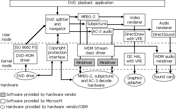
Figure 30.6 Implementation of the DVD support architecture
Advanced features of DVD include multi-angle, multiple audio tracks, and multiple subpicture tracks. For more information about DVD features, see Chapter 12, "Multimedia."
Note
Some components in the DVD architecture will change based on advances in other hardware technologies, such as WDM support for the PCI bus under Windows 98. The only components that will always be present are the DVD-ROM driver, the Universal Disk Format (UDF) file system, the WDM Stream class driver, and the DVD Splitter/Navigator.
The following components comprise support for DVD movie playback under Windows 98:
DVD-ROM class driver.
DVD-ROM has its own industry-defined command set, supported through an updated CD-ROM class driver. This driver provides the ability to read data sectors from a DVD-ROM drive.
UDF file system.
Support for UDF ensures support for UDF-formatted DVD discs. UDF takes advantage of packet writing and is the industry standard for compact disc storage. As with FAT and FAT32, Windows 98 provides installable file systems for UDF.
WDM Stream class driver.
The WDM Stream class driver supports streaming data types, and MPEG-2 and AC-3 hardware decoders. Hardware vendors have to write only a small amount of interface code in a minidriver to ensure that the specific features in their hardware are supported. This allows most DVD decoders to work without user intervention.
DirectShow.
Microsoft DirectShow (formerly ActiveMovie) proxy filters and related support include a DVD Navigator/Splitter, proxy filters for video streams, a video mixer, and a video renderer. The proxy filters allow programs written to the DirectShow API to control kernel mode filters.
DirectDraw Hardware Abstraction Layer (HAL) with Video Port Extensions (VPE). Decoded video streams are huge—possibly too large even for the PCI bus on a computer. Manufacturers have solved this problem by creating dedicated buses to transfer decoded video streams from an MPEG-2 decoder to the display card. Microsoft provides software support for these interfaces using the DirectDraw HAL with VPE.
Copyright protection.
Copyright protection for DVD is established when key sectors on a disk are encrypted (as with Macrovision), then decrypted before the sectors are decoded. Microsoft provides support for both software and hardware decrypters using a software module that enables authentication between the decoders and the DVD-ROM drives in a computer.
Regionalization.
As part of the copyright protection scheme used for DVD, six worldwide regions have been set up by the DVD Consortium. Disks are playable on DVD devices in some or all of the regions according to regional codes set by the content creators. Microsoft provides software that responds to the regionalization codes as required by the DVD Consortium and as part of the decryption licenses.
DVDPlay.
Microsoft provides a DVD movie playback application, which can be replaced with another DVD playback application written to DirectShow2.
Under Windows 98, DVD-ROM is simply a large storage medium, much like CD-ROM. To enable DVD-ROM as a read-only device, Microsoft provides support for DVD-ROM devices in Windows 98 and support for UDF as an installable file system. Using DVD-ROM device drivers, a DVD-ROM drive is treated as another peripheral, using industry-defined methods to access DVD disks and handle encrypted content.
The streaming of data involves loading an application responsible for handling large amounts of data in a constant load, or stream, over time. The application never loads the data completely into memory; the data file is too large, and the operations on the data file are typically sequential. The best example of this for DVD is an MPEG-2 video stream. When a computer plays an MPEG-2 file, a program loads and streams the MPEG-2 data across the computer to be decoded and displayed. The data might enter and exit the host processor and bus of the computer several times during this process. In addition, an MPEG-2 stream starts out at approximately 5 to 10 Mbps. After the stream is decoded, the data transfer rate can easily exceed 100 Mbps. A single data stream this large can saturate and overwhelm a computer’s PCI bus; this means an alternate path might be required for the raw, decoded video data.
A single stream demands a potentially large and constant load on a computer, over what could be considered a long time in computer terms. For DVD, the system must be able to independently manage and decode at least four separate streams:
This must be done so the streams are totally synchronized when they reach their final destinations, with no dropped frames or degraded video. This requires precision in load balancing, synchronization, and processing.
The WDM Stream class driver can deal with these problems because it is optimized to work with any devices that use streamed data. Such devices include those that encode data (for example, video capture devices), and those that decode data (for example, DVD hardware decoders that decode MPEG-2 streams for playing DVD movies). This class driver uses the WDM layered architecture for interconnecting device drivers to optimize data flow within the Windows 98 kernels.
Because Windows 98 supports USB and the IEEE 1394 bus, it can support digital audio. USB and IEEE 1394 have the bandwidth necessary to support digital audio and have mechanisms to provide synchronization between an audio source and an audio sink. Both provide different forms of isochronous and asynchronous services that can be used by distributed audio systems.
The following describes the attributes of USB that allow it to accommodate digital-audio devices.
Capacity.
With a total transfer rate of 12 Mbps, USB has enough capacity for consumer audio but would be inappropriate for multitrack audio production. Unlike with IEEE 1394, adding nodes to a USB network does not add to the total data-carrying capacity of the network.
Synchronization.
Although USB uses a 1-ms master clock for synchronization, the burden of synchronization is placed on the host computer. USB provides three modes of synchronization:
Digital signal processing (DSP) capability.
With USB, DSP must take place in the end nodes or in the host. For example, if a DVD drive and a home stereo were connected to a host, and the user wanted to play an AC-3 audio-encoded stream, the AC-3 decoding could take place in either the host or in the stereo set, but not in an intermediate DSP dongle (a device, attached to a computer’s I/O port, that adds hardware capabilities). The USB requirement for DSP connection is in contrast with the IEEE 1394 bus requirement, in which DSPs can also be connected as interior members of the daisy-chain or tree.
USB device classes.
If a device conforms to a defined USB device class, Plug and Play methods can be used to identify the device and load a device driver. This eliminates the need for device manufacturers to ship driver disks with their products.
Intel support.
Intel built the USB host controller into the latest Triton chip set, which interfaces the Pentium processor to the PCI bus and motherboard. Because USB is a serial bus, having its controller as part of this chip set adds very few pins and adds negligible cost to the computer motherboard.
Intel also built the 82930 microcontroller into USB. This chip has all the logic necessary to interface with USB and send and receive data. Vendors can combine the standard USB code with code necessary to control their devices. The 82930 microcontroller can provide complete communications and control for consumer or industrial devices.
Appliances as computer peripherals with USB Open Standards.
Windows 98 supports OpenHCI and UHCI. Detailed hardware descriptions of the USB interface have been published so that smaller companies can integrate USB into their custom chips without extensive design work.
Not only is USB designed for standard devices, such as joysticks, keyboards, printers, and mouse devices, but because of its low production cost and relatively simple implementation, USB enables a wide class of devices to become computer peripherals. For example, a postage meter containing microcontrollers can have a USB port added for a small increase in cost. Connected to a computer, the meter can become part of a company-wide cost-tracking system. Adding voice output to the postage meter for use by a blind operator requires connecting the postage meter to a computer containing USB audio hardware. A programmer can add audio by using application programming interfaces (APIs) under Windows 98.
If the postage meter conforms to the HID class, Plug and Play support ensures that the device is recognized as soon as it is plugged into the computer. When that occurs, Windows 98 loads in a device driver, configures the device, and makes it available to end-user software. This is particularly useful for telephones. A telephone is both an HID (the keypad) and an audio USB device. It might also include a conventional, ISDN, or high-speed cable modem. If a telephone answering/fax machine has a USB port, the device works fine on its own, but when plugged into a computer, it becomes a modem, a scanner, a printer, and a more intelligent answering machine.
Home entertainment.
The home stereo system is another consumer device that already contains a microcontroller and can be easily upgraded to connect to a computer running Windows 98 with USB. Except for the audio data rates, a stereo system is not much different from a telephone with USB. When equipped with a USB interface, a stereo system becomes a USB audio class device and an HID-class device. The microcontroller inside a stereo system is not much different from the microcontroller inside a keyboard; the stereo system microcontroller spends most of its time polling buttons, waiting for the user to change the volume or tone controls.
The following describes the attributes of the IEEE 1394 bus that allow it to accommodate digital-audio devices.
Capacity and synchronization.
With the IEEE 1394 bus, it is possible to put a CD drive on one node and a digital-to-analog converter (DAC) on another node. The clocks of both devices can be slaved to the master clock on the bus. Because the IEEE 1394 bus is designed to handle video data (a transfer rate of 400 Mbps), handling multiple tracks of audio is a much simpler task. IEEE 1394 networks can be configured using multiple buses and filtering bridges in a leaf-node configuration so many devices can play in parallel without passing data over the same segment of the bus.
DSP capability.
Arbitrary amounts of DSP power can be applied to streams of audio by means of IEEE 1394 dongles. DSPs inside a computer are limited by the total memory of the system and must compete with the CPU for this resource. On the IEEE 1394 bus, signals can be passed between nodes containing DSPs. Each DSP node increases delay to the processing time, but the IEEE 1394 bus can string many DSPs together.
Home entertainment.
Microsoft is working with Sony, Yamaha, and Texas Instruments to define standards for home entertainment audio delivery over the IEEE 1394 bus. Microsoft is also working with OEMs and third-party software developers to make Windows 98 the best platform for delivery of multimedia content.
Aside from continuing support of the conventional display features found in Windows 95, Windows 98 supports a new and important display feature called Multiple Display Support. The ability to run multiple applications on the computer has made screen space a precious commodity. It would be convenient to be able to view all your running applications at the same time and not have to keep clicking between windows. The costly solution is to use a very large (35-inch, for example) video monitor; a more economical and flexible solution is to connect two or more smaller monitors to the computer so that each application can be viewed on its own screen, or the entire desktop can be viewed across all the screens. The latter solution is the Multiple Display Support feature.
Multiple Display Support uses the concepts of a primary display and secondary display. For you to be able to use a monitor as a secondary monitor, it must meet certain criteria. It must be a PCI or AGP device, and it must be able to run in GUI mode or without using VGA resources. It must also have a Windows 98 driver that enables it to be a secondary display. For a list of these drivers, see "Technical Notes on Multiple Display," in Chapter 24, "Device Management."
The system BIOS picks the primary VGA display based on the PCI slot order, unless the BIOS offers an option for picking which device is to be treated as the VGA device. Also, an important consideration for docking units is that the VGA device cannot be stopped.
As shown in Figure 30.7, Multiple Display Support allows the Windows 98 desktop to cover more than one monitor with no restrictions on size, position, resolution, or refresh rates. You can configure the system to the size and relative position of each monitor and move applications seamlessly from one monitor to another.
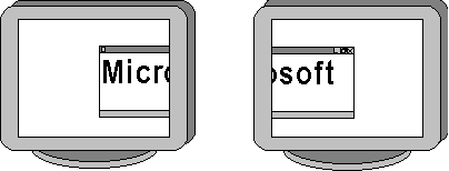
Figure 30.7 Example of Multiple Display Support
On a single-monitor system, the actual desktop is the same size and shape as the only monitor on the system. On a Multiple Display Support system, each monitor is actually a view onto the underlying virtual desktop. You can use the Windows 98 Control Panel to set the area that each monitor presents. As shown in Figure 30.8, the primary monitor always has coordinates corresponding to 0,0 for the upper-left corner, and the x and y resolution for the lower-right corner. The actual coordinates viewed on the secondary monitors depend on the layout of the monitors, which you set using Control Panel. The layout of the secondary monitors is usually based on the physical layout of the monitors on the user’s desk.

Figure 30.8 A virtual desktop containing three monitors
You can use Control Panel to change the resolution of any of the monitors, but you can change only the coordinates of the secondary monitors. Although both the primary and the secondary monitors use a coordinate system, only the secondary monitors allow their position in the virtual desktop to be changed. The primary monitor's top-left coordinates must remain 0,0 for compatibility. In addition, all the monitors must touch each other on the virtual desktop. This restriction allows the system to maintain the illusion of a single, large desktop that you can seamlessly cross from one monitor to another. At no point do you lose track of the mouse as you move it between monitors.
You can attach up to nine monitors in a multiple display configuration. The coordinates for the second monitor continue from a starting position adjacent to the primary; the coordinates for the third monitor continue from a starting position adjacent to the second monitor, and so on. Since the desktop area that each monitor actually views must be adjacent to another monitor, the virtual desktop is the bounding rectangle of all rectangular areas that can be seen on all attached monitors. For example, if both the primary and secondary monitors have a resolution of 1024 x 768, then a secondary monitor attached to the right of the primary monitor has coordinates from (1024,0) to (2047,767).
If a monitor is not aligned on an axis with its adjacent monitor, or if there are monitors with different resolutions, some of the virtual desktop area might not have a monitor that views that area. For example, the system shown in Figure 30.9 has a 1024 x 768 primary monitor, and an 800 x 600 secondary monitor. The primary monitor has coordinates (0,0) to (1023,767), and the secondary monitor, which is attached to the left of the primary, has coordinates (-800,167) to (-1,767). This results in an area with coordinates from (-800,0) to (-1,167) that is not displayed on either monitor. Windows 98 will not let the user move the mouse into this area, but the area is included in the calculation of the virtual desktop. Therefore the virtual desktop for the example system has coordinates from (-800,0) to (1023,767).
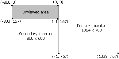
Figure 30.9 Unviewed Virtual Desktop area with monitors of unequal resolution
A smart card is a small electronic device, approximately the size of a credit card, that contains an embedded integrated circuit. Smart cards are used for such tasks as storing medical records, storing digital cash, and generating network IDs.
The following is a list of system requirements for smart card support:
Windows 98 provides the necessary files to enable smart card–aware Windows applications and for service providers to communicate with smart cards through readers attached to Windows-based computers.
The base components on a CD-ROM require a device driver from a smart card reader manufacturer. No device drivers are currently included in Windows 98, but several companies have readers and device drivers available.
You also need a Smart Card Service Provider (SCSP) or Smart Card Cryptographic Provider (SCCP) to expose the services of a smart card to a Windows-based application. The service providers are distributed by the card supplier or issuer and pertain to non-cryptographic and cryptographic services.
Note
To develop a device driver or service provider, you must obtain a licensed copy of the Smart Card DDK and Smart Card SDK.
 To install the Microsoft smart card components
Install may replace the Advpack.dll system file.
 To uninstall the Microsoft smart card components
The Smclib.sys and Smclib.vxd files, used by smart card reader drivers, are not removed during Uninstall, because device drivers that depend on these files to start and run may still be installed on the system. The files may be removed after all smart card reader device drivers have been removed.
The Msvcrt.dll and Mfc42.dll files are not removed by Uninstall, because they are shared resources.
The Advpack.dll system file is not removed by Uninstall.
Windows 98 supports still image (STI) devices under the WDM architecture. An STI device requires that a minidriver of the WDM STI class be written. Current examples of STI devices are:
For more information about writing device drivers for Windows 98, see the Windows 98 DDK.
The STI architecture reduces the software investment made by a hardware vendor. It helps focus the vendor’s work on designing device features rather than dealing with system-related tasks. Figure 30.10 illustrates the STI architecture.
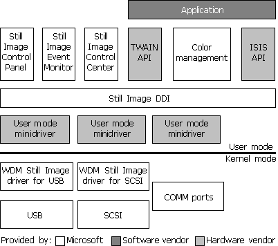
Figure 30.10 STI architecture
The following describes the components shown in Figure 30.10:
Application.
Two primary types of applications use still images. One type is for the editing of image data. Examples of this type are Adobe PhotoShop and Microsoft PictureIt! The other type is for authoring documents that include image data, but that do not focus on editing that image data. Examples of this type are word processing and page layout applications, such as Microsoft Word, or a presentation application, such as Microsoft PowerPoint®.
Still Image APIs.
TWAIN, ISIS, and Adobe Acquire are the common API interfaces in use today. Currently, a hardware vendor has to supply a device-specific component that implements a driver for each supported API.
Color Management.
This interface and implementation maintains device color profiles and provides for color-space conversion. All color output from scanners must be defined. To accomplish this, a scanner must either create RGB output or embed the International Color Consortium (ICC) profile for the scanned image into the image file to identify the color-space information for that image.
Still Image Control Panel.
In Windows 98, the Control Panel icon Scanners and Cameras gives you access to the following for installed STI devices:
The icon appears in Control Panel when Windows 98 detects a Plug and Play STI device, or when you install a non-Plug and Play, STI device through the Add New Hardware Wizard.
For more information about the Add New Hardware Wizard, see Chapter 24, "Device Management."
Still Image Event Monitor.
This application (provided by Microsoft) supports push-model behavior by detecting events coming from installed STI devices, and dispatching a set of those events to an application. From Control Panel, you can configure which Still Image-compliant applications are invoked.
Still Image Device Driver Interface (DDI).
This DDI (provided by Microsoft) is used to communicate with a particular device. The Still Image APIs, the Control Panel, and the Event Monitor use the Still Image DDI. This DDI uses the color management system as a repository for the color profile supplied for a specific device. The DDI provides interfaces for the following:
User-Mode minidrivers.
These vendor-written modules are small components used to implement device-specific DDI functionality (test, status, and data I/O).
Still Image kernel-mode drivers.
These Microsoft-provided modules package a command or data for delivery on a specific bus type. All new kernel-mode drivers provided by Microsoft are WDM-based, although kernel-mode drivers generally need not be. Vendors must supply their own kernel-mode drivers for devices that are not designed to use the standard Microsoft kernel-mode drivers for a specific bus. Currently, kernel mode drivers for SCSI and USB are provided specific to still image devices.
Bus drivers.
These Microsoft-provided modules are used to communicate with the STI device. Examples are the USB driver stack, serial-port drivers, and parallel-port drivers.
Video Capture under Windows 98 is based on the WDM Stream class driver. Windows 98 provides minidrivers for USB and IEEE 1394 cameras, as well as PCI and videoport analog video devices. Support includes DirectShow filters for WDM video-capture interfaces, and for backward compatibility, a Video for Windows (VFW)-to-Stream class mapper. The mapper currently works only with the USB and 1394 digital cameras, and not with the PCI or videoport analog video devices.
Capture applications have been developed using both DirectShow and VFW. Newer capture and conferencing applications are expected to migrate to using the DirectShow interfaces. A sample DirectShow capture application (Amcap.exe) is included in the DirectShow SDK.
Vidcap32.exe is a sample VFW capture application included in the Win32 SDK. It allows you to capture video sequences and images from a VCR, videodisc player, or video camera. Video Capture provides two modes for capturing video sequences:
Real-time capture processes a video sequence and audio as the events occur naturally or as the video source plays without interruption. A video source for real-time capture (such as a video camera or videodisc) provides an uninterrupted stream of information to the capture hardware. The capture hardware copies each frame of the video sequence (and each portion of audio) and transfers it to the hard disk before the next frame of data enters the capture hardware. A video frame contains one image of the video sequence.
Real-time capture demands a fast computer and hard disk. The computer must process and store each incoming video frame before the next frame is received in the capture board. If the system lags during capture, frames of video data are lost.
Step-frame capture pauses the video source as it collects each frame (image) of data. If audio is also selected, this capture mode rewinds the media in the video source and collects audio data as the video source plays a second time. Step-frame capture collects video frames from a video sequence in a series of steps. Frames are captured one at a time, generally from a paused video device. You can perform step-frame capture manually, advancing the video source using the controls on the video device. Video Capture also provides automatic step-frame capture for video devices that support the Media Control Interface (MCI). With this method, Video Capture issues frame-advance commands to the source device and captures the sequence frame-by-frame. When Video Capture finishes capturing the current frame, it advances the video source to the next capture point.
Step-frame capture provides an alternative for systems that cannot process a video sequence in real time. Because the system can fully process a video frame before contending with the next frame, you can use larger frame sizes and color formats, and you can optionally compress the video sequence during capture. When a step-frame capture is complete, you can capture the audio segment associated with the video frames by playing the source video a second time.
For more information about configuring and using Video Capture, see the Help file Vidcap.hlp included in the Windows 98 SDK.
Windows 98 supports Accelerated Graphics Port (AGP), a high-performance, component-level interconnect for 3-D graphics applications. Microsoft provides code in Windows 98 that enumerates and initializes devices on the AGP bus. Windows 98 is also responsible for initializing the AGP hardware and managing the mapping from system memory to the video hardware address space. This support is mostly behind the scenes and is not directly accessible to applications programmers. The AGP functionality can be incorporated into applications through the Microsoft DirectDraw API.
Through a hardware-capability bit, DirectDraw allows a graphics driver to indicate that it supports AGP. A DirectDraw driver can specify one or more video memory heaps to DirectDraw that describe how it can address AGP memory. A DirectDraw-based application can specify whether it wants a surface allocated in local video memory, non-local video memory, or system memory. If none of these is specified, DirectDraw chooses the memory class for the surface, and the application can query to find out where the surface was allocated.
AGP allows the graphics processor to see system memory by using the Graphics Address Relocation Table (GART). The GART takes all the virtual pages and makes them look like a contiguous region of memory to the graphics accelerator. The CRTC on the display card does not see the GART.
There are two type of GART memory: Uncached and Write Combined. The data is written straight through to memory for Uncached memory. Multiple writes are combined in a buffer for Write Combined memory. This buffer is controlled by the memory management unit. The advantage of Write Combined is that it is a lot faster to transfer (for example, eight DWORDS at a time as opposed to one DWORD at a time).
In Windows 98, the GART is split evenly between Uncached and Write Combined. The maximum size of the GART is controlled by the BIOS. Some BIOSs allow the AGP aperture (maximum size) to be set. The Graphics Processor can use the GART for texture memory.
Windows 98 provides support for IrDA, the Infrared Data Association standard for wireless connectivity. IrDA support allows Windows 98 users to connect hardware devices and other computers easily without using connecting cables. This driver set provides infrared-equipped portable or desktop computers with the ability to network, transfer files, and print wirelessly with other IrDA-compatible infrared devices. For example, the user of an IrDA-equipped portable computer can simply walk up to an IrDA-equipped printer, aim the computer at the printer (in the same manner as aiming a TV remote control at a TV), and run the print function. Another example is a user copying a file from one portable computer to another by aiming the first computer at the other and then running the copy function.
Hardware Profiles are used to set up multiple hardware configurations. This is especially useful for portable computers that have docking stations or workstations with removable storage media.
Hardware Profiles are automatically created for portable computers when the system is docked or undocked. Furthermore, a new hardware profile would be created if the computer is placed in a different docking station.
The following procedures demonstrate how to set up hardware profiles for a portable computer with a docking station that has this configuration:
| Configuration | Docked | Undocked |
|---|---|---|
| Display driver | S3 | VGA |
| Network | Microsoft Network | None |
| RNA | No RNA | With RNA |
 To set systems properties
 To set up the video driver for docked and undocked configurations
 To set up for no network in an undocked state
 To set up for no RNA while docked
Tip
Windows 98 scans for floppy drives on each boot, which is helpful for portable computers and other computers where the floppy can be removed. If you are on a desktop with a stationary floppy drive, you can turn this option off to speed up boot time.