Lighting in Direct3D
Microsoft Corporation
April 1998
Introduction
The appearance of elements in a Direct3D® scene is controlled by numerous variables. One of these variables is the material you use to shape your object. A material describes the illumination properties of a surface, including how it handles light and whether it uses a texture. For a detailed discussion of materials, see the DirectX® SDK.
Surfaces in your Direct3D application are illuminated by the lights you create. This white paper provides a technical explanation of how to use lighting parameters and compute vertex colors for Direct3D application programmers. For further discussion of lights, fog, or lighting tips, see the Direct3D SDK.
Overview
Direct3D computes a color for each unlit vertex. This is accomplished by applying an equation defined by a client-specified lighting model to a set of parameters that can include the vertex coordinates, the parameters of the light sources, the current normal, and the current material.
Lighting is currently done in the model space because of performance issues. Light source direction and position are transformed to the model space by multiplying by inverse world matrix. If the world matrix is not orthogonal, this process will produce incorrect colors.
Lighting Parameters
Tables 1 through 3 below describe parameters used in the lighting equations. For each parameter there is a corresponding type, default value, and a range of acceptable values.
Table 1. Notations
| Parameter |
Default value |
Type |
Description |
|
Pe
|
(0,0,0)
|
D3DVECTOR
|
Camera position in camera space.
|
|
Po
|
(0,0,0)
|
D3DVECTOR
|
Position of the current model origin.
|
|
Mw
|
N/A
|
D3DMATRIX
|
World matrix, set by D3DTRANSFORMSTATE_WORLD.
|
|
Mv
|
N/A
|
D3DMATRIX
|
View matrix, set by D3DTRANSFORMSTATE_VIEW.
|
|
S
|
N/A
|
D3DVECTOR
|
Scale, extracted from the world matrix.
|
|
halfway
|
N/A
|
D3DVECTOR
|
Normalized vector, used to compute specular reflection.
|
|
La
|
(0.0, 0.0, 0.0, 0.0)
|
D3DCOLORVALUE
|
Ambient color in the light state. Set by D3DLIGHTSTATE_AMBIENT.
|
|
V
|
N/A
|
D3DVECTOR
|
Vertex position.
|
|
N
|
N/A
|
D3DVECTOR
|
Vertex normal.
|
|
Vcd
|
N/A
|
D3DCOLORVALUE
|
Vertex diffuse color.
|
|
Vcs
|
N/A
|
D3DCOLORVALUE
|
Vertex specular color.
|
Table 2. Material parameters
| Parameter |
Default value |
Type |
Description |
|
Ma
|
(0.0, 0.0, 0.0, 0.0)
|
D3DCOLORVALUE
|
Ambient color.
|
|
Md
|
(0.0, 0.0, 0.0, 0.0)
|
D3DCOLORVALUE
|
Diffuse color.
|
|
Ms
|
(0.0, 0.0, 0.0, 0.0)
|
D3DCOLORVALUE
|
Specular color.
|
|
Me
|
(0.0, 0.0, 0.0, 0.0)
|
D3DCOLORVALUE
|
Emissive color.
|
|
Mp
|
0.0
|
D3DVALUE
|
Specular exponent. Range:  . .
|
|
Mr
|
0
|
DWORD
|
Ramp size. Range: [0, 256].
|
Table 3. Light source i parameters
| Parameter |
Default value |
Type |
Description |
|

|
(0.0, 0.0, 0.0)
|
D3DVECTOR
|
Position in world space.
|
|

|
(0.0, 0.0, 0.0)
|
D3DVECTOR
|
Direction in world space.
|
|

|
0.0
|
D3DVALUE
|
Distance range. Range:
[0.0, D3DLIGHT_RANGE_MAX].
|
|

|
(0.0, 0.0, 0.0, 0.0)
|
D3DCOLORVALUE
|
Color.
|
|

|
0.0
|
D3DVALUE
|
Constant attenuation factor. Range:  . .
|
|

|
0.0
|
D3DVALUE
|
Linear attenuation factor. Range:  . .
|
|

|
0.0
|
D3DVALUE
|
Quadratic attenuation factor. Range:  . .
|
|

|
0.0
|
D3DVALUE
|
Falloff factor. Range:  . .
|
|

|
0.0
|
D3DVALUE
|
Umbra angle of spotlight in radians. Range:  . .
|
|

|
0.0
|
D3DVALUE
|
Penumbra angle of spotlight in radians. Range:  . .
|
Notes
A range of D3DCOLORVALUE component is  .
.


norm(P)—normalized vector

 —inverse matrix
 —transposed matrix
V1/V2 , where V1 and V2 are of D3DVECTOR type, and are equal to the vector:
(V1.x / V2.x, V1.y / V2.y , V1.z / V2.z)
V1 * V2 , where V1 and V2 are of D3DVECTOR type, and are equal to the vector:
(V1.x * V2.x, V1.y * V2.y, V1.z * V2.z)
State Update
Every time the transformation state, light sources, or viewport is updated, the following computations are performed.
Computation of Inverse World Matrix
The world matrix could be represented as:
Mw = Mwr * Mwt, where Mwr is the rotation part and Mwtb is the translation part.
Inverse world matrix is computed as:

Note  only if the world matrix is orthogonal. If the world matrix has scale, the result will be incorrect.
The same formulas are used for the view matrix:

Compute Scale from the World Matrix
Scale vector is computed to offset errors produced by Direct3D computations in the case of a nonorthogonal world matrix.
For light 1:

For light 2:

where: j = -1 if the determinant of Mw is negative or 1. Otherwise:

Transform Lights to the Model Space
The transformation process differs for light 1 and light 2.
Light 1
Light position for all nondirectional lights is transformed to model space by:

The light direction is computed as:

Light 2
Light position for all nondirectional lights is transformed to model space by:

The light direction is computed as:

Transform Camera Position to the Model Space
The camera position is transformed to model space as:

Lighting Formulas
Output alpha is equal to the alpha component of diffuse material (Md.a), clamped to the range [0, 255].
The alpha component is not used in the following formulas.
For the point and spot lights 2, in the case of nonunit scale, the vertex position is multiplied by the scale:
V = V * S
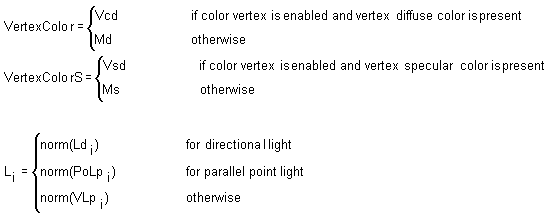
Diffuse component

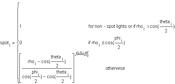
Specular component

where:

 are halfway vectors between the normal and the light directions:

 are computed differently for lights 1 and lights 2.
For lights 2:


For lights 1:


Diffuse and specular components are clamped to be from 0 to 255 and interpolated separately.
Ramp Lighting
Ramp lighting is performed only for Direct3D device 2.
For every material the following data is computed:
base – integer start index in the palette.
size – integer size of material ramp.
scale – size - 1, scale to convert intensity (0 ... 1) to the color index.
A shade value is computed for every light:

Ambient component is not computed.
Diffuse Component

Specular Component

 are computed as for RGB mode.
D and S are clamped to [0.0, 1.0] range.
If enabled, fog is applied.
The diffuse component of the output color is used to store combined diffuse and specular values.
The specular component of the output color is used to store texture handle or zero.

FOG
The following state is related to the fog:
In the light state:
D3DLIGHTSTATE_FOGMODE
One of the members of the D3DFOGMODE enumerated type. The default value is D3DFOG_NONE.
D3DFOG_NONE
D3DFOG_EXP
D3DFOG_EXP2
D3DFOG_LINEAR
D3DLIGHTSTATE_FOGSTART
Defines the starting value for fog. The default value is 1.0.
D3DLIGHTSTATE_FOGEND
Defines the ending value for fog. The default value is 100.0.
D3DLIGHTSTATE_FOGDENSITY
Defines the density setting for fog. The default value is 1.0.
In the render state:
D3DRENDERSTATE_FOGENABLE
Setting the value to TRUE enables fog. The default value is FALSE.
D3DRENDERSTATE_FOGCOLOR
A value of type D3DCOLOR. The default value is 0.
D3DRENDERSTATE_FOGTABLEMODE
One of the members of the D3DFOGMODE enumerated type. The default value is D3DFOG_NONE.
D3DRENDERSTATE_FOGTABLESTART
Position in fog table at which fog effects begin for linear fog mode. Specify a position in the fog table with a value between 0.0 and 1.0. This render state enables the exclusion of fog effects for positions close to the camera. For example, setting this value to 0.3 will prevent fog effects for positions between 0.0 and 0.299.
D3DRENDERSTATE_FOGTABLEEND
Position in fog table beyond which fog effects end for linear fog mode. Specify a position in the fog table with a value between 0.0 and 1.0. Using this render state, you can set a position in the fog table beyond which fog effects will not increase. For example, you can set this value to 0.7 to prevent additional fog effects for positions between 0.701 and 1.0.
D3DRENDERSTATE_FOGTABLEDENSITY
Sets the maximum fog density for linear fog mode. This value can range from 0 to 1.
D3DRENDERSTATE_RANGEFOGENABLE
To compute the correct distance from eye to a vertex.
If fog is enabled by setting D3DRENDERSTATE_FOGENABLE to TRUE, and D3DRENDERSTATE_FOGTABLEMODE is set to D3DFOG_NONE, the following scenarios are possible:
- D3DLIGHTSTATE_FOGMODE is set to D3DFOG_NONE. If a transformed vertex is passed to Direct3D, the alpha component of the specular color is used as fog factor. If a nontransformed vertex is passed, the prior DX6 alpha component of the diffuse color of the material is copied to the alpha component of the specular color in every vertex, and is used as fog factor.
- If D3DLIGHTSTATE_FOGMODE is not D3DFOG_NONE, fog factor is computed for every vertex after lighting is applied.
- If D3DLIGHTSTATE_FOGMODE is not D3DFOG_NONE, per-pixel fog is computed.
Per-Vertex Fog Implementation
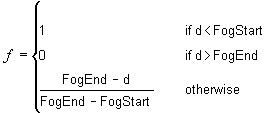
Fog factor in a vertex is a function of the distance between camera position and vertex. This distance can be approximated by Z value in camera space. For per vertex fog, we compute  in camera space by transforming the vertex using Mworld*Mview, and then computing the distance to the vertex.
Distance from the camera to a vertex V is computed as:

Fog factor is computed as:

In RGB mode, fog factor f is scaled to be in the range [0, 255] and written to the alpha component of the specular output color.
In Ramp mode, diffuse and specular components are multiplied by the fog factor and are clamped to be in the range from [0.0, 1.0].
D = D*f
S = S*f
-------------------------------------------------------------------------------------------------
© 1998 Microsoft Corporation. All rights reserved.
The information contained in this document represents the current view of Microsoft Corporation on the issues discussed as of the date of publication. Because Microsoft must respond to changing market conditions, it should not be interpreted to be a commitment on the part of Microsoft, and Microsoft cannot guarantee the accuracy of any information presented after the date of publication.
This White Paper is for informational purposes only. MICROSOFT MAKES NO WARRANTIES, EXPRESS OR IMPLIED, IN THIS DOCUMENT.
 .
.


 .
.
 .
.


 —inverse matrix
 —transposed matrix
 only if the world matrix is orthogonal. If the world matrix has scale, the result will be incorrect.


 are halfway vectors between the normal and the light directions:
 are computed differently for lights 1 and lights 2.


 are computed as for RGB mode.
 in camera space by transforming the vertex using Mworld*Mview, and then computing the distance to the vertex.
