Doug Yoder
Microsoft Corporation
September 1999
Summary: This article walks through the creation of a Microsoft® Visual Basic® 6.0 application that takes advantage of the core set of services available in the Microsoft Access 2000 Workflow Designer for Microsoft SQL Server™ version 7.0. When completed, you will have a simple Visual Basic application that illustrates how to use these services in Visual Basic. To complete this walkthrough, you should be familiar with creating applications in Visual Basic. (40 printed pages)
Introduction
What Is a Team Solution?
Step 1: Design the Grid Form
Step 2: Build the Workflow Toolbar
Step 3: Design the Detail Form
Step 4: Test Workflow Functionality
Step 5: Provide Offline Access
Step 6: Enable Data Synchronization
Step 7: Test Offline Functionality
Conclusion
For More Information
The Microsoft® Access 2000 Workflow Designer for Microsoft SQL Server™ 7.0 provides a robust core set of services that can be used to build powerful tracking solutions. The solution developed, the team solution, and its associated user interface typically are described as a Web site that contains a set of data access pages developed using Microsoft Access 2000. However, solutions using the Microsoft Access Workflow Designer extensions can be developed using a number of different development tools, depending on the requirements of the users and the features desired in the solution.
One such development tool is Microsoft Visual Basic® 6.0, which is one of the most popular development tools for the Microsoft Windows® platform. This article provides a walkthrough on how to build an application in Visual Basic that takes advantage of the core features available in the Microsoft Access Workflow Designer. After completing the walkthrough, you will have created a complete Visual Basic application that takes advantage of workflow features. This sample application has been kept basic, so you can apply these concepts to your own applications.
This article walks you step-by-step through the process of building an application in Visual Basic that uses features available in the Microsoft Access Workflow Designer. The code snippets throughout the article are provided for you to copy and paste into your application without having to retype them.
This article does not explain how to create a database using the Microsoft Access Workflow Designer, but it explains how to build an application using an existing database. The application uses the Issue Tracking database provided as a template with the Microsoft Access Workflow Designer. For details about using the template, see the Microsoft Access Workflow Designer online documentation.
To follow the procedures in this article and create the Visual Basic application, you must have the following software and components installed on the server and client:
A team solution is an application that uses one or more of the features provided by the Microsoft Access Workflow Designer—for example, workflow and offline capabilities. A typical team solution created using the Microsoft Access Workflow Designer has a SQL Server database and a user interface created using data access pages.
The Microsoft Access Workflow Designer tools help you add these features to your database; but to use them in your Visual Basic application, you must expose this functionality to the user.
Using Visual Basic as the interface has drawbacks. Microsoft Access Workflow Designer can be used to create a template of a team solution. A solution template makes it possible for users to create additional applications easily from a pre-defined solution that has been created into a template. The Microsoft Access Workflow Designer can create templates only from solutions that have a Web site interface. Therefore, the Visual Basic application created using this article cannot become a template. However, you could deliver a Visual Basic team solution by creating a template of the Microsoft Access Workflow Designer database and then separately distributing the Visual Basic application that uses that database.
The Visual Basic team solution created in this article is structured in a similar manner to the Web-based Issue Tracking solution provided as a template in the Microsoft Access Workflow Designer. The application contains the following user interface elements: a Grid form (Form1) that shows a summary of issues and a Detail form (Form2) that shows details about a specific issue. The user interacts with the database through these two forms.
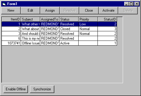
The Grid form uses the Hierarchical FlexGrid control to provide a list of the Issues in the Issue Tracking database. Along the upper portion of the Grid form, a series of command buttons provides access to actions defined for the workflow process. This series of buttons is referred to as the workflow toolbar. The lower portion of the Grid form contains two buttons that control the offline behavior of the application. See Figure 1.

Figure 1. Grid form (Form1)
Although the completed Grid form is simple, it does provide you with an understanding of how to use the features of the Microsoft Access Workflow Designer in Visual Basic.
The Detail form is a data-bound form that is used to view and modify individual rows in the Issue Tracking database. It is displayed by selecting one of the actions listed on the workflow toolbar on the Grid form. Because nearly all of the Microsoft Access Workflow Designer functionality is implemented in the Grid form, only minimal time is spent on creating this form. See Figure 2.
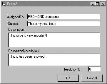
Figure 2. Detail form (Form2)
The Grid form is used to provide a list or summary of all issues stored in the Issue Tracking database. The form is a standard Visual Basic form with a Hierarchical FlexGrid control. The data binding is done using the Data Environment designer.
The Data Environment designer provides a design-time interface for specifying the data you want to access at run time. The designer generates Microsoft ActiveX® Data Objects (ADO) Connections, Commands, and recordsets at run time that you can manipulate programmatically.
In addition, Visual Basic provides a way for developers to automatically bind Command objects defined in the Data Environment to data-aware controls on a form. This makes it possible to display data on a Visual Basic form without any programming.
Note If this menu item is not available, you must make the Data Environment designer available from the Components dialog box. Select Components from the Project menu, and then in the Designers tab, select Data Environment. See Figure 3.
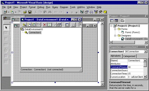
Figure 3. Data Environment menu item
A new Data Environment is always created with one Connection object named "Connection1." The Connection object defines which SQL Server and database contains the data to use.
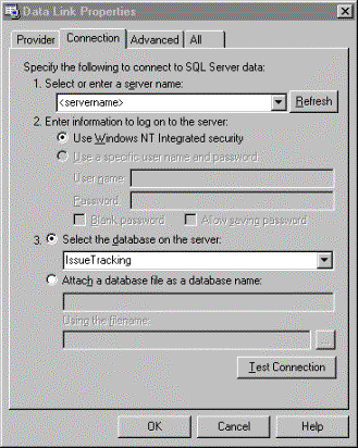
Figure 4. Data link properties
The Connection object defines the database to access. A Command object must be defined that specifies which table or view to access. For example, in the Issue Tracking database, the IssuesBaseView view should be used. This view contains all fields in the Issues table and all the lookup tables (such as Category, Priority, and Status).
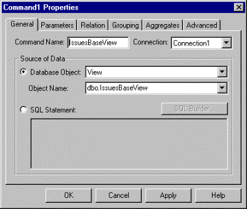
Figure 5. Command properties page
The Data Environment window lists the IssuesBaseView Command and all fields within the view under it. See Figure 6.
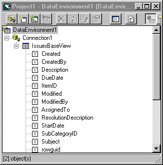
Figure 6. Data Environment with IssuesBaseView listed
The data returned from the IssuesBaseView is now available in the application using this Data Environment object.
The Hierarchical FlexGrid Microsoft ActiveX control provides an easy way to display multiple rows of data from a data source, because it supports direct binding to an ADO object defined in a Data Environment object. The control also provides built-in property pages that make it easier to format the fields you want displayed within the grid.
A Hierarchical FlexGrid control is created on the form. In addition, because dragging the IssuesBaseView node from the Data Environment created it, the grid automatically binds to the data from that view.
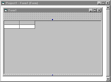
Figure 7. Form with Hierarchical FlexGrid control at design time
Using the Hierarchical FlexGrid control property pages, the run-time display and behavior of the grid can be modified.
Setting these properties makes it possible for the user to select only one row at a time in the grid and ensures the entire row is highlighted.
In addition, you can change the grid to show only certain fields from the IssuesBaseView and change the order of the fields displayed.
The fields available in the IssuesBaseView to which the control is bound are displayed in the grid. This is the default layout of the fields in the grid.
Note This step is important for later in the walkthrough, because this example will not work if the ItemID field is not the first field in the grid.
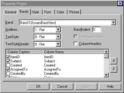
Figure 8. Formatting the Hierarchical FlexGrid control
The fields listed in the grid change to those you selected in the property page.
The basic design of the Grid form is now complete. Select Start from the Run menu to run the application.
Form1 displays a list of the issues in your database. If you have not entered any issues in the database, then none are listed. Note that only those fields selected are displayed. If you have issues in the database and you click a row, the entire row is highlighted. This is the behavior enabled by the FocusRect and SelectionMode property settings. See Figure 9.
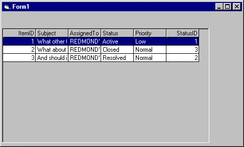
Figure 9. Grid form at run time
Now that the basic Grid form is working, it is time to add some Microsoft Access Workflow Designer-specific functionality. The workflow toolbar makes the actions that have been defined for the workflow process available to the user. In the case of the Issue Tracking database, the actions defined include Resolve, Close, Edit, Active, and so on.
Two main steps are required to build the workflow toolbar. The first step is to execute a set of queries against the database that returns information about the workflow process (such as the actions defined), and the second step is to use the information returned to build the toolbar dynamically.
Just as the Data Environment designer was used to define the data to specify what data to display in the Hierarchical FlexGrid control, the Data Environment is also a great way to read the workflow information. It provides a way to define visually the queries required, and it simplifies the code required to read the information.
In this example, the same Data Environment object is used to retrieve the IssuesBaseView data as is used when adding an additional Command object to it. Alternatively, you could create an additional Data Environment object if you want to keep a logical separation between "user data" and "workflow information" queries.
A new item, Command1, is listed under Connection1.
SELECT IssuesWorkflowActions.Caption, Min(Event) As Event,
Min(Position) As Position
FROM IssuesWorkflowActions
INNER JOIN IssuesWorkflowView ON
IssuesWorkflowActions.WorkflowId = IssuesWorkflowView.Id
GROUP BY IssuesWorkflowActions.Caption
ORDER BY 3
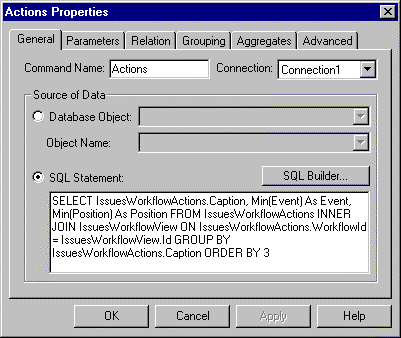
Figure 10. Actions Command property page
This Command object, Actions, is used to return a list of all of the available actions defined for the workflow process associated with the Issues table.
The IssuesWorkflowActions table contains a row for each action defined in the process, and the Caption field specifies the text that should be listed in the user interface. The IssuesWorkflow table contains the workflow rules along with other information required for each action, such as the workflow event fired for a particular action. Therefore, a two-table join is used to combine the tables, so all the information required is returned in one query.
SELECT IssuesWorkflowActions.Caption, IssuesWorkflowView.State,
IssuesWorkflowView.Next_State
FROM IssuesWorkflowView
INNER JOIN IssuesWorkflowActions ON
IssuesWorkflowView.Id = IssuesWorkflowActions.WorkflowId
WHERE (State = ?) OR (State = -1)
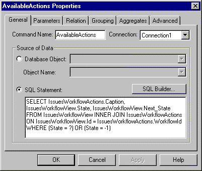
Figure 11. AvailableActions Command property page
This Command object, AvailableActions, is used to read the actions dynamically that are available based on a specific state. For example, in the Issue Tracking database, if a row has a state of Active (StatusID = 1), the available actions include Resolve and Edit but not Close or Activate.
The question mark included in the SQL SELECT statement is a query parameter, which can be provided at run time to alter dynamically the WHERE clause each time the Command is executed.
SELECT IssuesWorkflowView.Id, Status.Status, IssuesWorkflowView.State,
IssuesWorkflowActions.Caption, IssuesWorkflowView.Next_State, IssuesWorkflowView.Event
FROM IssuesWorkflowView
LEFT OUTER JOIN Status ON
IssuesWorkflowView.Next_State = Status.StatusID
INNER JOIN IssuesWorkflowActions ON
IssuesWorkflowView.Id = IssuesWorkflowActions.WorkflowId
WHERE (IssuesWorkflowActions.Caption = ?)
AND (IssuesWorkflowView.State = ? OR IssuesWorkflowView.State = - 1)
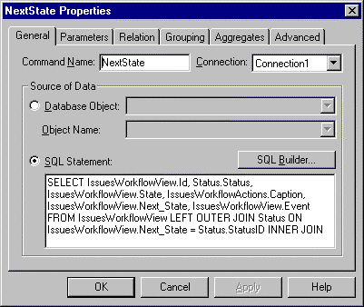
Figure 12. NextState Command property page
This Command object, NextState, is used to retrieve the next state value when transitioning from one state to another. For example, in the Issue Tracking database, when the user executes the Resolve action, it means the StatusID field of the row is changing from 1 to 2. This query is used to identify that 2 is the next value for the StatusID field.
Note This SQL SELECT statement also uses parameters to supply dynamically the WHERE clause at run time.
When you have completed these steps, the Data Environment object contains the original IssuesBaseView Command object along with the three new Command objects: Actions, AvailableActions, and NextState. See Figure 13.
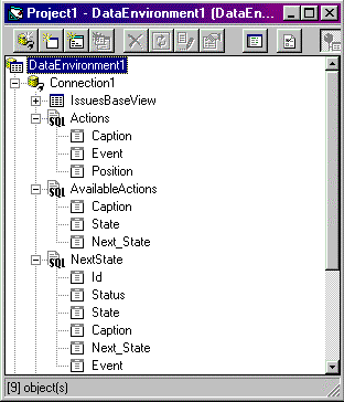
Figure 13. Data Environment with Workflow Commands
The workflow information is now available using the Command objects in the Data Environment object. The next step is to use the information returned to build a user interface that lists the available actions.
The user interface created here contains a control array of a series of CommandButtons—one for each action. This is a very basic example, but it provides the concepts required to create more elaborate interfaces. Most of the work is done using code at run time, because at design time, it is unknown what actions are available.
At design time, only one button is created, which is used as a template. For each action available, the CommandButton is copied and moved next to the previous one to form a series of buttons across the upper portion of the form.
Changing the Index property to 0 causes the CommandButton to become a control array that can contain multiple command objects at run time.
Public Function BuildActions() As Variant
    Dim DataEnvironment1 As New DataEnvironment1, intControl As Integer
    DataEnvironment1.Actions
    intControl = 0
    While Not DataEnvironment1.rsActions.EOF
        If intControl <> 0 Then
            Load cmdAction(intControl)
            cmdAction(intControl).Top = cmdAction(intControl - 1).Top
            cmdAction(intControl).Left = _
  cmdAction(intControl - 1).Width + cmdAction(intControl _
  - 1).Left
        End If
        With cmdAction(intControl)
            .Visible = True
            .Enabled = True
            .Caption = _
  DataEnvironment1.rsActions.Fields("Caption").Value
            .Tag = DataEnvironment1.rsActions.Fields("Event").Value
        End With
        intControl = intControl + 1
        DataEnvironment1.rsActions.MoveNext
    Wend

End Function
This routine accomplishes the following:
Private Sub Form_Load()
    BuildActions
End Sub
This causes the BuildActions routine to be executed when the form is first loaded.
Test the building of the workflow toolbar by running the Grid form. Select Start from the Run menu to run the application.
You should see a series of buttons along the upper portion of the form that list each of the actions available in the workflow process of the Issue Tracking database. See Figure 14.
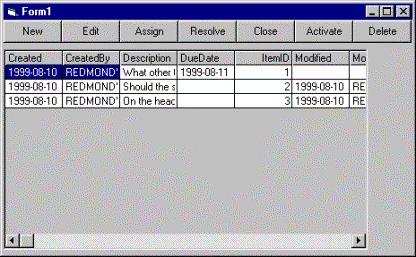
Figure 14. Actions in Issue Tracking database
Whether an action listed on the workflow toolbar is available depends on the currently selected issue. Only valid actions for the selected issue should be available. For example, if an issue is Active, then Closed is disabled, because it is not a valid action during the Active state. The CommandButtons on the toolbar must be enabled and disabled based on the currently selected issue.
Private Sub UpdateActions(intState As Integer)
    Dim DataEnvironment1 As New DataEnvironment1, intControl As Integer
    DataEnvironment1.AvailableActions intState
    For intControl = 0 To cmdAction.UBound
        cmdAction(intControl).Enabled = False
    Next
    While Not DataEnvironment1.rsAvailableActions.EOF
        For intControl = 0 To cmdAction.UBound
            If cmdAction(intControl).Caption = _
  DataEnvironment1.rsAvailableActions.Fields("Caption")._
  Value Then
                cmdAction(intControl).Enabled = True
            End If
        Next
    DataEnvironment1.rsAvailableActions.MoveNext
    Wend
End Sub
This routine accomplishes the following:
Private Sub MSHFlexGrid1_RowColChange()
    DataEnvironment1.rsIssuesBaseView.MoveFirst
    DataEnvironment1.rsIssuesBaseView.Find "ItemID = " + _
       CStr(MSHFlexGrid1.TextMatrix(MSHFlexGrid1.Row, 0))
    UpdateActions _
       DataEnvironment1.rsIssuesBaseView.Fields("StatusID").Value
End Sub
This routine accomplishes the following:
MSHFGrid1_RowColChange, so it contains:
Private Sub Form_Load()

    BuildActions

    MSHFlexGrid1_RowColChange

End Sub
This makes sure the toolbar is updated not only when the user changes the selected row, but also when the form is first loaded.
Make sure to place the RowColChange command after the execution of BuildActions. Otherwise, no buttons will be available.
Now you are ready to test it out. Select Start from the Run menu. You will see the workflow toolbar with the appropriate actions enabled and the others disabled. Select an issue that has a different status, and the workflow toolbar automatically updates. See Figure 15.
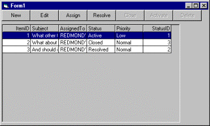
Figure 15. Running the form with updated actions
This completes the building of the primary functionality of the Grid form. The next step is to create the Detail form and make it possible for the execution of the actions by displaying the Detail form when an action is selected on the workflow toolbar.
The Detail form is used to view and modify one issue at a time. Similar to the Grid form, the Detail form is bound to the IssuesBaseView Command object in the Data Environment. However, instead of being bound to a grid, the fields are bound to individual TextBox controls.
By default, Command objects created in the Data Environment are read-only. An additional setting and a line of code are required to make the Command object updateable.
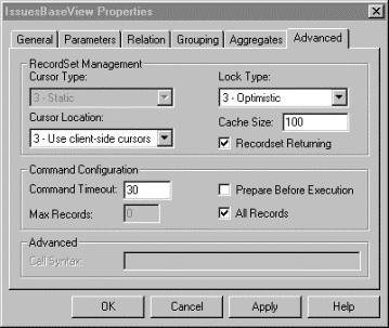
Figure 16. Advanced Command property page
In addition to setting the Lock Type property, another property value must be changed.
One of the features of the Microsoft Access Workflow Designer makes it possible for users to set row-level permissions. This functionality is enforced through a view that only returns the rows to which the user has access, based on the row-level permissions.
To prevent users from bypassing the row-level permissions and viewing rows to which they do not have access, the base table does not make read or write permissions possible to any users.
In the case of the Issue Tracking solution, the base table Issues is not accessible, but the views IssuesView and IssuesBaseView are accessible. To make updates to the Issues table view, IssuesBaseView, the Command object must be told to make updates only using the primary key of the base table. To do this, change the property setting to the Update Criteria property.
This property must be set whenever the Command object is opened. This can be done by adding code to the Initialize event in the module behind the Data Environment.
Private Sub DataEnvironment_Initialize()
    DataEnvironment1.rsIssuesBaseView.Properties("Update Criteria") = 0
End Sub
The Detail form can be created in a similar manner as the Grid form—by dragging the Data Environment onto a form.
A TextBox control is created on the form with a label, with a caption of "AssignedTo." The TextBox is set up automatically to bind to the AssignedTo field.
| Field |
| AssignedTo |
| Subject |
| Description |
| ResolutionDescription |
| ResolutionID |
Form2 contains five text boxes and looks similar to the following one in Figure 17, depending on how you placed the fields on the form.
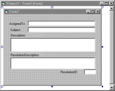
Figure 17. Form 2 with fields from IssuesBaseView
The Detail form will be accessed from the Grid form. The user must have a way to save changes made to the row and then close the Detail form.
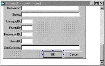
Figure 18. OK and Cancel buttons on the Detail form
Private Sub cmdCancel_Click()
    DataEnvironment1.rsIssuesBaseView.Cancel
    Unload Form2
End Sub
Private Sub cmdOK_Click()
    DataEnvironment1.rsIssuesBaseView.Update
    Unload Form2
End Sub
The cmdCancel routine accomplishes the following:
The cmdOK routine accomplishes the following:
For each action defined on the workflow toolbar, there is an associated event. The event associated with the action defines the functionality that is executed. The events and typical functionality are as follows:
For each of these events, except OnDelete, the user should have the opportunity to view and modify all fields from the Issues table. In addition, for the OnTransition event, the next state based on the current state of the row must be identified, and the workflow field must be updated with this new state.
The actions are executed by clicking a button on the workflow bar, which is built using the cmdAction control array. Therefore, code must be added on the cmdAction_Click event that identifies the button clicked and executes functionality based on the event associated with the button action. Remember that when the workflow toolbar is generated, the Tag property of the control array is set to the event associated with the action. Code must retrieve this value and, based on the value, execute the appropriate functionality.
Private Sub cmdAction_Click(Index As Integer)
    Select Case cmdAction(Index).Tag
        Case "OnCreate"
            Load Form2
            DataEnvironment1.rsIssuesBaseView.AddNew
            Form2.Show vbModal, Me
This section of the routine accomplishes the following:
        Case "OnUpdate"
            Form2.Show
Continuing this routine accomplishes the following:
        Case "OnDelete"
            If MsgBox("Are you sure?", vbYesNo, "Delete Issue") = _
                vbYes Then
                DataEnvironment1.rsIssuesBaseView.Delete
            End If
This code does the following:
Add the following code:
        Case "OnTransition"
            intState = _
              DataEnvironment1.rsIssuesBaseView.Fields("StatusID").Value
            strCaption = cmdAction(Index).Caption
            DataEnvironment1.NextState strCaption, intState
            intNextState = _
              DataEnvironment1.rsNextState.Fields("Next_State").Value
            DataEnvironment1.rsIssuesBaseView.Fields("StatusID").Value _
              = intNextState
            Form2.Show vbModal, Me
        End Select
This code accomplishes the following:
    DataEnvironment1.rsIssuesBaseView.Requery
    Set MSHFlexGrid1.DataSource = DataEnvironment1
    MSHFlexGrid1.DataMember = "IssuesBaseView"
    MSHFlexGrid1_RowColChange
End Sub
This code accomplishes the following:
The previous steps complete all workflow functionality for the application. Follow the next steps to test the functionality.
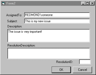
Figure 19. Detail form at run time
Note The Issue Tracking database contains workflow scripts that require the value of the AssignedTo field to be associated with a user in the user directory. If you enter a user to the AssignedTo field who is not in the user directory, you will receive an error message. See Figure 20.
Note Because this code does not have any error-checking for this, you must click End to stop the application and then restart it. To complete your application, you must add error-checking routines to handle such errors appropriately.
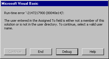
Figure 20. Error received when invalid AssignedTo value is entered
After you successfully add the issue to the database, you will have a new row in the Grid form with a status of Active, the default for new rows.
The Detail form appears with the new row you added. Although it looks as if the row is being edited only, the code has executed a workflow transition automatically by changing the StatusID field from 0 (Active) to 1 (Resolved). This change is not committed until you click OK.
You must enter a value for these fields, because the Issue Tracking solution contains workflow scripts that validate these fields on a transition from Active to Resolved. See Figure 21.
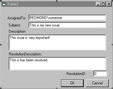
Figure 21. Resolving an issue
The Grid form is updated, and you will see the status of the issue you entered has changed from Active to Resolved. In addition, the workflow toolbar has been updated automatically to reflect the change.
Test the rest of the actions available by selected issues and clicking actions on the workflow toolbar.
Offline access is the second major functionality provided by the Microsoft Access Workflow Designer. Enabling offline access in your application requires two steps. First, enable offline access by replicating a local copy of the network database. Then, have your application dynamically change its connection information to use the local copy when running offline. Once the database is available offline, functionality is required to make it possible for the user to synchronize any changes made to the network database.
To use the offline features of the Microsoft Access Workflow Designer, the user must install the client run-time components. These components include a COM object (MODReplSvr 1.0) that is used to set up offline access and provide the synchronization of data. In addition, the user must have a copy of the Microsoft Data Engine (MSDE) or the desktop version of SQL Server installed. This is used to store the local copy of the database.
Users must have a way to enable offline access if they have not taken the application offline before. This functionality is enabled using a CommandButton on the Grid form.
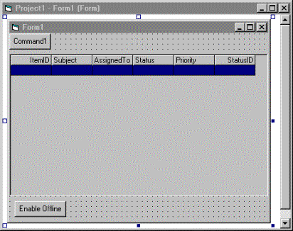
Figure 22. Grid form with the Enable Offline button at design time
As mentioned earlier, a Microsoft Access Workflow Designer run-time COM object is used to enable and maintain the offline functionality. To use this COM object in the application, a reference in this project must be made to this COM object.
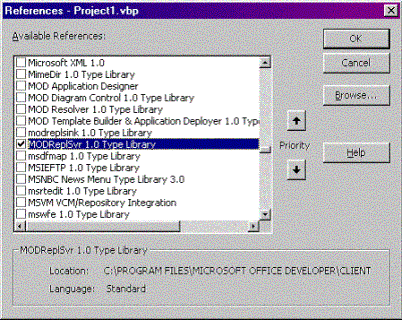
Figure 23. References dialog box
Selecting this COM object enables access to this object and the methods associated with it. Code in the Click event of the Enable Offline CommandButton uses this COM object to enable offline access.
Private Sub cmdOffline_Click()
    Dim oReplSvr As New MODReplSvr
    Dim strServer As String, strDB As String
    strServer = _
      DataEnvironment1.Connection1.Properties("Data Source").Value
    strDB = _
      DataEnvironment1.Connection1.Properties("Initial Catalog").Value
    oReplSvr.Init strServer, strDB
    oReplSvr.DeleteAllSubscriptions
    oReplSvr.RegisterSubscription 0
    oReplSvr.CreateSubscription
    oReplSvr.DoInitialSync
End Sub
This function accomplishes the following:
When the offline database has been created, the application must provide a way for users to specify to use the offline database rather than the network database. One way is to prompt the user when the application is started to make the choice to work offline or online. You may want to provide a less intrusive interface for this, but this will give you the basics on what you must do to redirect your application to use the offline database.
When the user wants to use the offline database, the application must dynamically change the connection information stored in the Data Environment objects in the project to use the local database rather than the network database. To do this, the connection information must be changed before the connections are established. One way to change the connection is by adding code to the form's Initialize event that checks to see whether the application has been enabled for offline use and, if so, prompts the user to indicate whether to use the offline or online database.
The actual redirection of the connection information does not happen in the Initialize event but in the Data Environment objects. The Form_Initialize routine sets up a global variable to identify whether to use the offline or online database. Later, code is added to the Data Environment object to check this global variable and make changes to the connection objects based on it.
Public gOffline As Boolean
Private Sub Form_Initialize()
    If IsOfflineEnabled() Then
        If MsgBox("This application is enabled for offline use. " + _
             "Would you like to work offline?", _
             vbYesNo) = vbYes Then
            gOffline = True
        Else
            gOffline = False
        End If
    End If
End Sub
This routine accomplishes the following:
As mentioned, a custom function is required to verify whether the application has been enabled for offline access. First, the function determines whether the online database has been enabled for offline. This information is saved in a Microsoft Access Workflow Designer modSystem table. Second, if the online database has been enabled for offline access, the function determines whether the current client has subscribed to the online database by running the Enable Offline routine added earlier.
To retrieve this information, three separate queries are run—two against the online database and one against the local database. These queries will be added as Command objects in the Data Environment object.
SELECT * FROM modProperties WHERE Name LIKE 'OfflineEnabled' AND Value = 1
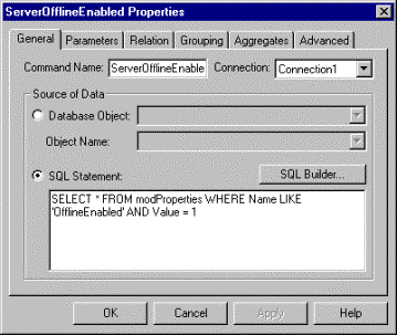
Figure 24. ServerOfflineEnabled Command property page
This Command object queries the modProperties table and finds a row where the property name is OfflineEnabled and the value is 1. If a row is found, offline has been enabled for the online database.
exec sp_modReplSubscribed ?
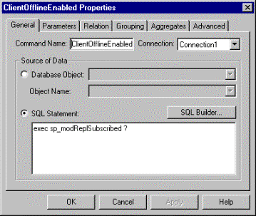
Figure 25. ClientOfflineEnabled Command property page
This Command object executes a stored procedure that uses a parameter to provide some information at run time. The parameter specifies what the current client SQL Server name is, which is what the online server uses to identify clients that have subscribed to it.
To find out the name of the local SQL Server, a query must be executed—not against the online database but to the local SQL Server (or MSDE). Because Connection1 inside the Data Environment connects to the online database, a second Connection object must be created that connects to the local data source.
Using (local) for the server name specifies to use the local SQL Server no matter what the local computer is named. The database selected must be one that is always present, whether or not the database has been taken offline. In that case, the master database is used, because it always exists. See Figure 26.
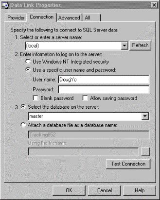
Figure 26. Data Link properties for local SQL Server
SELECT @@SERVERNAME As ServerName
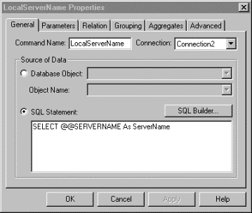
Figure 27. LocalServerName Command properties
The query for this Command object returns the name of the SQL Server in the form of a recordset.
After these three Command objects are created, the DataEnvironment1 window will look similar to the one in Figure 28:
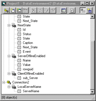
Figure 28. Data Environment with new Command objects
The queries required to verify whether the application is enabled for offline access are completed. Next, the custom function must be added that uses these Command objects to return whether the user has enabled the application for use offline.
Function IsOfflineEnabled()
    DataEnvironment1.ServerOfflineEnabled
    If DataEnvironment1.rsServerOfflineEnabled.RecordCount > 0 Then
        DataEnvironment1.LocalServerName
        If DataEnvironment1.rsLocalServerName.RecordCount > 0 Then
            DataEnvironment1.ClientOfflineEnabled _
              DataEnvironment1.rsLocalServerName.Fields("ServerName")._
              Value
            If DataEnvironment1.rsClientOfflineEnabled.RecordCount _
              > 0 Then
                IsOfflineEnabled = True
            Else
                IsOfflineEnabled = False
            End If
        Else
            IsOfflineEnabled = False
        End If
    Else
        IsOfflineEnabled = False
    End If
End Function
This function accomplishes the following:
At this point, the application can identify whether it has been enabled for offline use, and if it has, it prompts users whether they want to use the offline database. What is missing is the actual work that redirects the connection objects in the Data Environment objects to use the local database when the user selects to use the offline database.
Remember that a global variable is used to identify whether the user wants to go offline or not. Code must be added to each Data Environment object that checks this global variable. If the variable is True, the code changes the server to be the local SQL Server.
Private Sub DataEnvironment_Initialize()
    If Form1.gOffline = True Then
        DataEnvironment1.Connection1.Properties("Data Source").Value _
          = "(local)"
    End If
    DataEnvironment1.rsIssuesBaseView.Properties("Update Criteria") _
        = 0
End Sub
The added code contains a simple IF statement that retrieves the global variable. If it is True, the Data Source property of the Connection1 object is changed to "(local)," which tells the connection to use the local SQL Server no matter what it is named. That is all that is required!
Offline support is nearly completed. The user can enable offline access to the data and start up the application that is using the data offline. The one last item required is a way to synchronize changes made offline with the online database. To do this, a Synchronize button can be added to the form that the user clicks to update the online database.
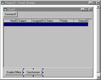
Figure 29. Grid form with a Synchronize button at design time
Private Sub cmdSynch_Click()

    Dim oReplSvr As New MODReplSvr
    Dim strServer As String, strDB As String
    strServer = _
      DataEnvironment1.Connection1.Properties("Data Source").Value
    strDB = _
      DataEnvironment1.Connection1.Properties("Initial Catalog").Value
    oReplSvr.Init strServer, strDB
    oReplSvr.Synchronize

End Sub
The code accomplishes the following:
That is it. Your application now has workflow and offline functionality.
The offline functionality is now complete in the application. The final step is to test that functionality.
The first time you run the application, you will not be asked whether you want to work offline, because offline features have not been enabled yet. When you first start the application, you will see the Grid form with the two new buttons added. See Figure 30.
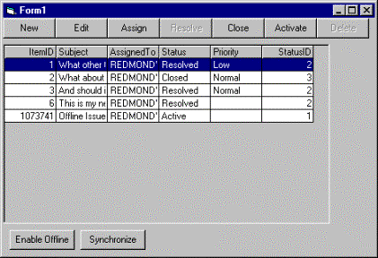
Figure 30. Grid form at run time with offline functionality
This may take some time, so be patient while the local database is set up for offline use. Note that the code does not provide feedback to the user. To make the application more user-friendly, you should consider adding such code. When the control returns back to the form, you will not see any noticeable differences.
A message box is displayed asking whether you want to work offline. See Figure 31.

Figure 31. Message box for choosing to work offline
The Grid form is displayed. Once again, you will not see any noticeable differences, but the data is being retrieved from the local database. To verify this, you can disconnect from the network and still access the data in the local store.
You will notice the rows you entered or modified while offline do not appear, because you are now working on the online database.
Again, this may take a bit of time. When control returns to the form, the grid will look the same, because no code was added to refresh the grid automatically.
The new row you added offline is available now in the online database. The online database was updated successfully with the changes you made to the offline database.
Although a Microsoft Access Workflow Designer team solution typically is described as a Web application, the team solution user interface can be developed using any development tool that can access SQL Server data. In this walkthrough, you created a Visual Basic application that takes advantage of the core set of services available in the Microsoft Access Workflow Designer—essentially becoming a team solution.
By reading workflow information, the application is able to generate dynamically a workflow toolbar that guides the user in following the workflow process defined in the database. Using the MODReplSvr COM object provided by Microsoft Access Workflow Designer, the application provides offline support and synchronization with the online database. And all of this functionality is tied around a set of data-bound Visual Basic forms to provide a complete application.
Take the basic concepts illustrated in this application, and create your own team solutions in Visual Basic or any other development tool that can access SQL Server data.
For the latest information about Microsoft Access Workflow Designer for SQL Server, see the Microsoft Office Developer Web site at http://msdn.microsoft.com/OfficeDev/.
To access Knowledge Base information, consult the Product Support section of the Microsoft Office Developer Web site.
For additional information about developing team solutions, consult the Access Workflow Designer Developer's Guide online documentation.